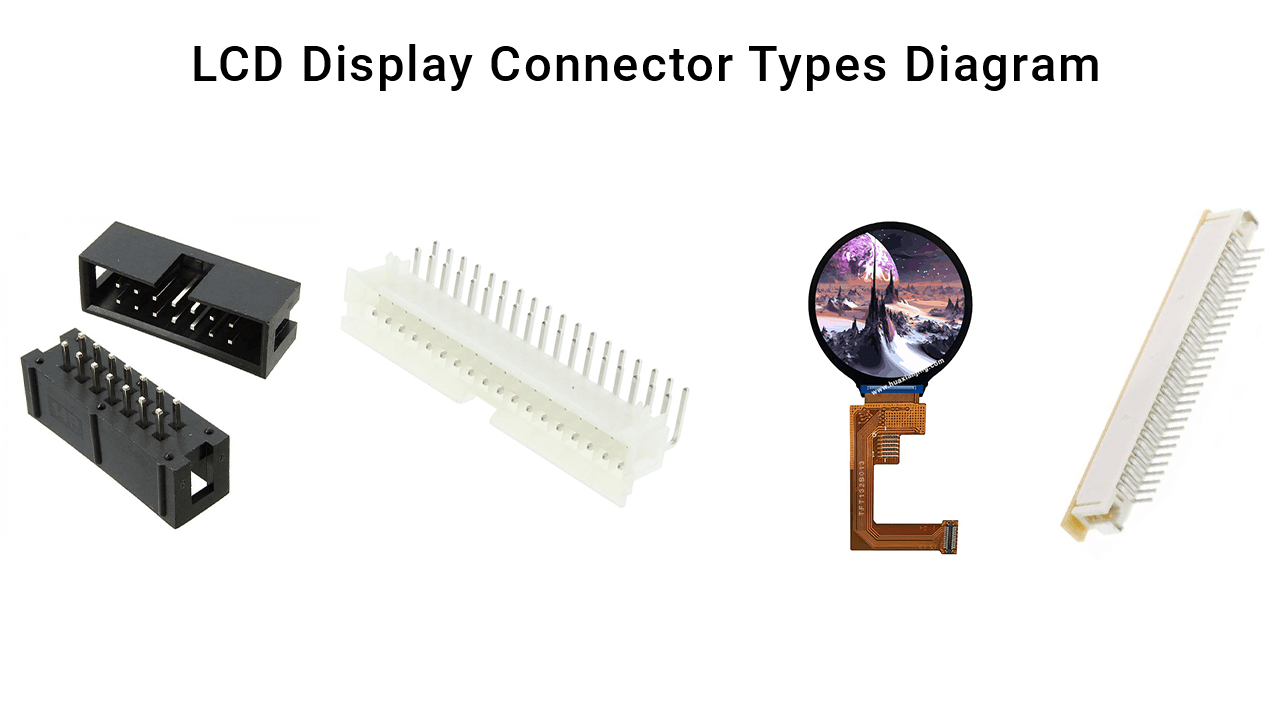
What are the most common types of LCD display connectors?
LCD display connectors include FFC/FPC, ZIF, BTB, and wire-to-board connectors. Each type has unique features and applications. Choosing the right one depends on factors like space, durability, and signal needs. Understanding these options helps in designing efficient and reliable systems.
Detailed Overview of Common Connector Types
- FFC/FPC Connectors
- Features : Flexible, slim, and lightweight. Pitch sizes range from 0.3 mm to 1.25 mm.
- Applications : Smartphones, tablets, and compact devices.
- Advantages : Space-saving, cost-effective.
- Challenges : Fragile during installation; proper alignment is critical.
- ZIF Connectors
- Features : Zero insertion force with locking mechanisms.
- Applications : Consumer electronics, devices requiring frequent assembly/disassembly.
- Advantages : Easy to use, reduces wear on connectors.
- Challenges : Locking mechanism must be secured to avoid connection loss.
- BTB Connectors
- Features : High durability, supports high-speed signals, available in stacking or perpendicular configurations.
- Applications : Industrial displays, automotive systems.
- Advantages : Robust and reliable.
- Challenges : Bulky and more expensive.
- Wire-to-Board Connectors
- Features : Easy to install and disconnect.
- Applications : Basic displays, low-cost designs.
- Advantages : Simple, widely available.
- Challenges : Limited for compact or high-tech designs.
How do you choose the right LCD connector for your application?
The right LCD connector depends on signal integrity, pitch, durability, and mounting style. For compact designs, use FFC/FPC. For frequent assembly, choose ZIF. Robust environments need BTB connectors. Analyze your system’s technical needs before finalizing a choice.
Key Factors to Consider When Selecting
- Signal Integrity
- Use connectors with shielding for high-speed data.
- Ensure impedance matching for stable signals.
- Pitch and Pin Count
- Match the connector pitch to the LCD module’s configuration.
- Ensure sufficient pins for power, data, and control signals.
- Durability
- Evaluate resistance to vibration and wear.
- Choose connectors rated for high insertion/removal cycles if needed.
- Environmental Resistance
- For harsh conditions, choose connectors with temperature and corrosion resistance.
- Mounting Style
- Opt for SMT for compact designs or THT for strong mechanical bonds.
What are the common challenges with LCD display connectors?
Challenges with LCD connectors include misalignment, signal noise, mechanical stress, and space constraints. Address these by using locking mechanisms, proper shielding, and vibration-resistant designs. Early testing ensures compatibility and reliability.
Detailed Solutions to Common Problems
- Misalignment During Assembly
- Problem: Connectors may not align perfectly, leading to poor contact.
- Solution: Use alignment tools or ZIF connectors with locks.
- Signal Noise or Loss
- Problem: Interference impacts high-speed transmission.
- Solution: Use connectors with built-in shielding and ensure proper grounding.
- Mechanical Stress
- Problem: Vibrations may loosen connections.
- Solution: Choose BTB connectors with robust locking systems.
- Space Constraints
- Problem: Limited space restricts connector size.
- Solution: Use compact FFC/FPC connectors.
Why are pitch and pin count important for LCD connectors?
Pitch and pin count determine compatibility and functionality. Matching the connector’s pitch to the LCD module ensures alignment. Adequate pin count supports power, data, and control signals. Misalignment or insufficient pins can cause malfunction.
Technical Details on Pitch and Pin Count
- Pitch Sizes : Commonly range from 0.2 mm to 2.54 mm. Smaller pitches save space but are harder to align.
- Pin Count : Varies based on the module’s interface. Ensure enough pins for all necessary connections.
- Recommendations : Use connectors with slightly more pins than required for future scalability.
How can signal integrity issues be prevented with LCD connectors?
Signal integrity issues arise from interference(how to reduce interference in pcb design), crosstalk, and poor grounding. Prevent them by choosing connectors with shielding, using impedance-matched designs, and optimizing PCB layouts. Testing during prototyping is essential.
Ensuring Signal Integrity
- Shielding : Blocks external interference for stable signals.
- Impedance Matching : Minimizes signal reflections and loss.
- Proper Layout : Maintain short and direct traces to reduce resistance.
What are the environmental considerations for LCD connectors?
LCD connectors in harsh environments need temperature, moisture, and corrosion resistance. For outdoor or industrial use, opt for sealed designs. Choose materials like gold plating for corrosion resistance and ensure proper insulation.
Durability Features for Harsh Environments
- Temperature Resistance : Rated for -40°C to +85°C for industrial use.
- Sealing : IP-rated connectors prevent dust and moisture ingress.
- Corrosion Resistance : Gold or nickel plating for long-term reliability.
How do mounting styles impact LCD connector selection?
Mounting styles, like surface-mount technology (SMT) or through-hole technology (THT), affect PCB design and reliability. SMT suits compact devices, while THT offers stronger mechanical connections for high-stress environments.
Comparing SMT and THT
- SMT : Small, lightweight, ideal for automated assembly.
- THT : Durable, suitable for high-vibration environments.
- Selection Tip : Use hybrid designs for mixed requirements.
How to test and validate LCD connectors before production?
Testing involves mechanical fit, signal stability, and environmental simulation. Use prototype boards to check alignment and performance. Environmental testing simulates extreme conditions to verify long-term reliability.
Validation Steps
- Prototype Testing : Verify mechanical alignment and signal performance.
- Environmental Testing : Simulate temperature, humidity, and vibration.
- Documentation : Record test results for future reference.
Conclusion
This guide provides detailed insights into LCD connector types, selection criteria, and solutions to common technical challenges. Implementing these principles will ensure optimal performance and durability for your application.