
Positive mode LCDs show dark content on a light background; negative mode shows light content on a dark background.

A TFT LCD requires custom driver software because its unique hardware, is not supported by generic, off-the-shelf drivers.
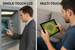
Single-touch screens recognize one touch at a time, while multi-touch screens can detect and respond to multiple touches simultaneously.
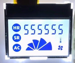
Designing your own custom segment LCD gives you total control over form and function.

LCD screen flickering stems from power supply instability, PWM dimming, refresh rate mismatches, or hardware failures
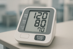
These medical LCD panels must meet strict requirements for image accuracy, regulatory compliance, and safety standards to ensure reliable diagnostic performance in healthcare environments.

HALT stands for Highly Accelerated Life Testing. It pushes LCDs to their limits using extreme conditions like heat and vibration.
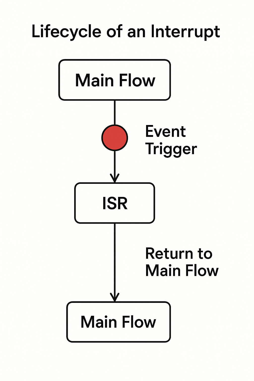
Interrupts manage time-sensitive tasks like LCD refresh and touch input in embedded firmware.
To program a graphic LCD module for custom graphics, start by picking a display that matches your microcontroller and meets your project needs.


