Introduction
The Electronic Industries Association set the RS-232 standard to help data terminal equipment (DTE)(What is Data Terminal Equipment (DTE)?), like computers, talk to data circuit-terminating equipment (DCE)(What is Data Circuit-Terminating Equipment (DCE)?), usually seen as modems. The use of this standard has grown since then. Today, RS-232 is often used to connect many devices, including LCD modules, through serial ports. This is especially common in industrial places.
Understanding RS-232 Basics
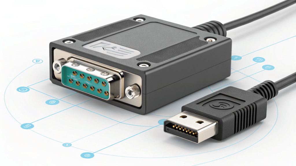
Before connecting multiple LCD modules with RS-232, it is important to understand the standard. RS-232, or Recommended Standard 232, is a way for devices to communicate. It sends data one bit at a time over a channel. It uses specific voltage levels to show digital data. This makes communication clear and reliable.
RS-232 is mainly for point-to-point connections. It works best for devices connected directly to each other. This setup avoids the complications of networking. While it is not as fast as modern options like USB, it is known for its simplicity and reliability. This makes it a good choice for connecting LCD modules, especially in industrial automation and embedded systems.
The Fundamentals of RS-232 Communication
RS-232 communication sends data as a series of bits through a cable. These bits stand for digital data and use specific voltage levels. The device that sends the data creates voltage changes, while the device that receives it reads these changes to recreate the original data. Both devices need to follow the same voltage standards for the data transfer to work well.
A major factor in RS-232 is the baud rate. This rate controls the speed of data transmission. It tells us how many signal changes, or bits, are sent each second. It’s very important to match the baud rates of both devices. For example, a common baud rate is 9600, meaning that 9600 bits are transmitted each second.
The voltage levels used in RS-232 are essential for safe data transmission. A binary 1, or logic high, uses TTL logic(Detailed Explanation of TTL Signal and LVDS Signal in LCD), negative voltage, usually between -3V and -15V. On the other hand, a binary 0, or logic low, uses positive voltage, often between +3V and +15V. This change in voltage levels from regular TTL logic means you need special RS-232 devices to convert the voltages correctly.
How RS-232 Works with LCD Modules

In electronics, devices that connect using RS-232 are split into two types: Data Terminal Equipment (DTE) and Data Circuit-Terminating Equipment (DCE). This split helps decide how data moves between devices. A computer is usually a DTE device, while a modem works as a DCE device. When adding an LCD module in an RS-232 system, the LCD generally acts as a DCE device, getting data from the DTE device, like a computer.
The process involves the DTE device sending commands or data to the LCD module. These commands tell the LCD to do things such as clear the screen, position the cursor, or show certain characters. The LCD module, getting these commands, understands them and changes what it shows.
For controlling data flow and avoiding loss, signals like RTS/CTS or DTR/DSR may be used. However, signals like Ring Indicator (RI) usually aren’t needed in a setup between the LCD and DTE. Instead, a simple 3-wire setup that uses TX, RX, and GND can work well when no extra flow control is needed.
How can multiple devices be connected using RS-232 communication?
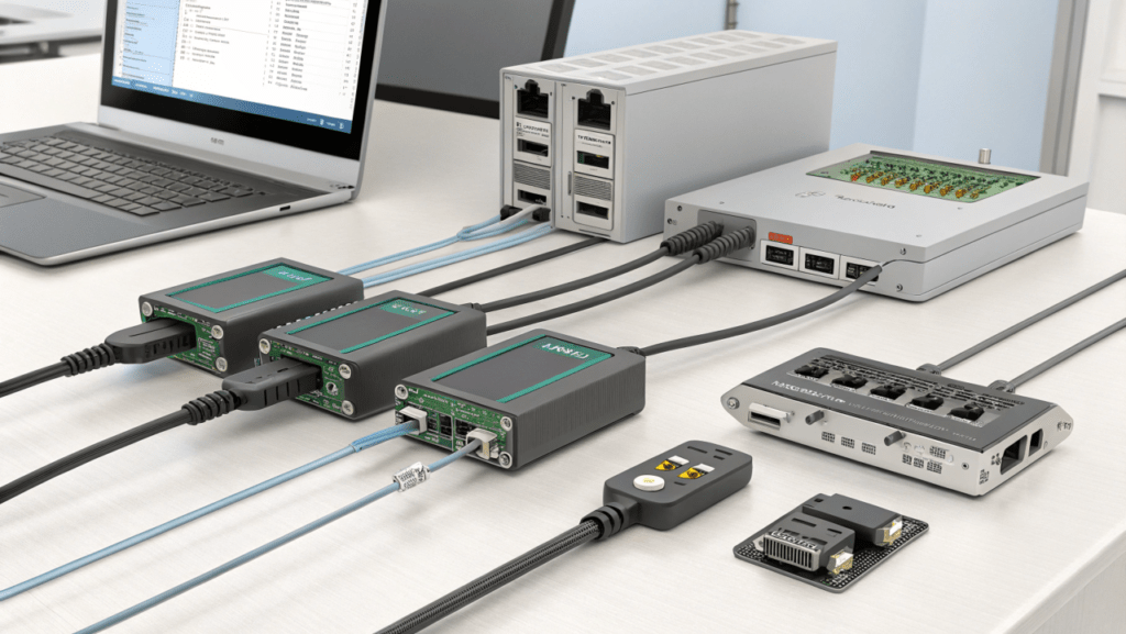
Multiple devices can be connected using RS-232 communication by daisy-chaining them together in a serial network. Each device has its own unique address, and data is transmitted serially from one device to the next. This method allows for efficient communication between multiple devices using RS-232 protocol.
Planning Your RS-232 Network
When setting up an RS-232 network to connect many LCD modules, careful planning is very important. You need to find out how many LCD modules you will use and how to place them. It is also important to think about things like cable lengths. Long cables can cause signal issues.
You should check if the controlling device (DTE) has enough serial ports. If not, look for USB-to-serial converters(What are USB-to-serial converters?) that can help. By planning this way, you will build a strong RS-232 network that will work well with the LCD modules.
Determining the Number of LCD Modules to Connect
When you plan your RS-232 network, the first step is to find out how many LCD modules you want to connect. RS-232 is usually for point-to-point communication. To connect multiple LCD modules, your data communication equipment (DCE), like a computer, needs enough serial ports or should work with USB-to-serial converters.
Each LCD module requires its own serial port to communicate properly. This means if you want to connect four LCD modules, your DCE should have at least four serial ports free. If your DCE doesn’t have enough ports, USB-to-serial converters can help, but setting them up might take more time.
Keep in mind that while RS-232 is simple and reliable, it doesn’t offer higher data rates compared to new technologies. If your project needs fast data transmission or needs to connect many devices, you might want to look into options like RS-485(What is RS-485?) instead.
Essential Components for RS-232 Connection
To connect LCD modules to your controlling device, you need a few important parts. First, you will need an RS-232 cable. This cable should have connectors that fit the ports on both your data communications equipment (DCE) and the LCD modules. If you are connecting a DTE device to a DCE device, a straight-through cable will work just fine. However, a null modem cable(What is a null modem cable?) is needed when connecting two DTE devices directly.
Null modem cables are special because they have wires that cross the transmit and receive lines. This allows two DTE devices to communicate as if there is a DCE device in between them. Since these cables can come in different setups, it’s important to choose the right type for your devices.
In addition to the cable, you must check the voltage levels. RS-232 uses different voltage levels than normal TTL logic. You may need voltage converters or level shifters to make sure the signals match between your devices. These converters help keep the DSR signal and other control signals at the correct voltages for clear communication.
Step-by-Step Guide to Connecting LCD Modules
Successfully connecting your LCD modules using RS-232 needs a step-by-step plan. First, know the pin setup for your LCD modules and the RS-232 port on your control device. This is very important, especially when using different connectors like DB-9 or DB-25(What are DB-9 and DB-25 connectors?).
Once you understand the pin setup, the next step is to make the physical connections with the right RS-232 cable. Make sure the connections match the correct transmit (TX), receive (RX), and ground (GND) pins on both sides. Paying close attention at this stage will help reduce communication problems later on.
Wiring RS-232 to LCD Modules
The first step to connect your LCD modules is to find the RS-232 pins on both the module and the control device (DTE). LCD modules usually have a connector. This could be a header or a terminal block for RS-232 communication. The DTE device will normally have a serial port, which is often a DB-9 or DB-25 connector. Check the documentation for both devices to get the pin assignments right.
In a typical setup, you connect the Transmit (TX) pin of the DTE device to the Receive (RX) pin of the LCD module. Then, the Receive (RX) pin of the DTE device goes to the Transmit (TX) pin of the LCD module. This way, the wiring is cross-connected, which is important for good communication.
Here is a common pin connection scheme:
- DTE TX –> LCD RX
- DTE RX –> LCD TX
- DTE GND –> LCD GND
Always pay close attention to wiring and understand pin configuration. This is important to avoid any communication errors. If you are unsure about a connection, it’s a good idea to read the documentation or ask a qualified person for help.
Configuring Each LCD Module for RS-232 Communication
Once the physical wiring is set up, it’s important to configure the communication settings on both the LCD module and the DTE device. This means you need to set things like baud rate(What is baud rate in serial communication?), parity, and the number of data and stop bits. These settings must be the same on both devices for sharing data successfully.
Start by checking the LCD module’s datasheet to find its default RS-232 settings. This will tell you things like the baud rate and parity. Next, set up the DTE device, whether it’s a computer or microcontroller, to match these settings. Make sure the TXD pin settings on the DTE device are correct for the RXD needs of the LCD module.
If the LCD module allows changes to its settings, you can adjust them to fit your needs. But make sure to update the DTE device settings as well to keep the communication steady. Depending on the DTE device, you may need special tools to help with configuration. For a computer, you might use Device Manager or specific terminal software.
Troubleshooting Common RS-232 Connection Issues
Even with careful planning, RS-232 connections can sometimes have problems. One common issue is signal integrity. This happens when cables are too long or don’t have enough shielding. These factors can cause signals to degrade and lead to communication errors.
Another issue, especially when using more than one LCD module, is the risk of communication conflicts. This occurs when several devices try to send data at the same time, which can corrupt the data. Finding out what causes these problems is the first step to fixing them.
Diagnosing Signal Integrity Problems
Diagnosing problems with signal quality in an RS-232 connection means checking the voltage levels of the sent and received data. Start by looking at the voltage levels on the DCE (Data Communication Equipment) side. A good signal should show voltage levels that follow the RS-232 standard. This means a negative voltage for logic high (Mark) and a positive voltage for logic low (Space). On the DTE (Data Terminal Equipment) side, these voltages will be flipped. Here, a positive voltage means logic high and a negative voltage means logic low.
If the voltage levels are off on either side, it may mean there is a problem with the signal. Another clear sign of trouble is when framing errors happen often. These errors show that there might be a timing problem, causing the receiver to mix up the start or stop bits of data. This can result from issues like the wrong baud rate settings or delays caused by long or poor-quality cables.
If you suspect there are signal issues, start with simple checks. Make sure the connectors are clean and are tightly joined. If the cable is longer than the 50-foot limit for RS-232 communication, use a shorter cable or a line driverto boost the signal. A careful approach that looks at voltage levels, framing errors, and cable quality is important to find and fix signal problems.
Resolving Multi-Module Communication Conflicts
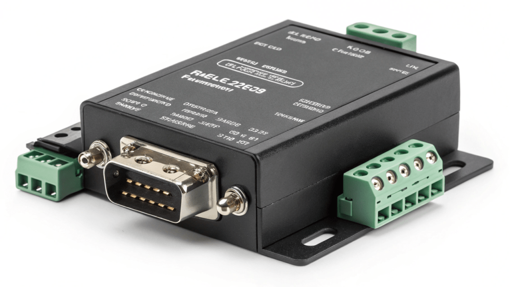
Communication conflicts can occur in setups with multiple LCD modules if the modules share a common communication line and attempt to transmit data concurrently. RS-232, fundamentally designed for point-to-point connections, faces challenges when multiple devices transmit on a shared line, leading to data collisions and rendering the information unintelligible.
To address this, employing a multi-drop configuration with appropriate hardware becomes crucial. This involves using RS-232 to RS-485 converters. RS-485, designed for multi-drop communication, allows multiple devices to share a single communication line while mitigating collision risks.
Direct connection of multiple LCD modules to a single RS-232 port on a PC is not feasible due to the risk of conflicts and potential damage to the PC’s serial port. The table below outlines potential issues:
| Issue | Description | Solution |
|---|---|---|
| Voltage conflicts | Multiple devices applying different voltages on the same line | Use diodes to isolate the TX lines |
| Data collision | Multiple LCDs transmitting data simultaneously | Use a microcontroller or RS-485 converter for controlled access |
| Ground loops | Multiple ground paths creating voltage differences | Ensure a common ground for all devices |
Resolving these issues often involves isolating the TX lines of each LCD using resistors or diodes to prevent voltage conflicts, and implementing proper grounding practices to avoid ground loops. If controlling the LCDs from a PC, a microcontroller can manage data transmission to individual LCDs, ensuring only one LCD transmits at a time, thus preventing data collisions.
Advanced Tips for Enhancing RS-232 Connectivity
Optimizing RS-232 connections means adjusting communication settings and using hardware to make them work better. Changing settings like baud rate and handshaking to fit your needs can help with data transmission.
If you need to use long cables or are in places with a lot of electrical noise, adding devices like repeaters or isolators can greatly improve the signal quality. Using these methods can make your RS-232 connections stronger and ensure data transmission stays reliable, even in tough situations.
Optimizing RS-232 Settings for Multiple Connections
Effectively managing several RS-232 connections requires balancing reliable communication with good data speed. One important factor is the baud rate. A higher baud rate can transfer data faster, but it may cause more errors if the distance is long or there is too much electrical noise. It’s important to choose a baud rate that meets the speed needs while still being strong enough for long-distance communication.
In addition to baud rate, using hardware flow control(What is hardware flow control in RS-232?) methods is very important, especially RTS/CTS (Request to Send/Clear to Send). These signals help avoid losing data by making sure the transmitter sends information only when the receiver is ready. Flow control is especially important when sending large amounts of data or when different LCD modules need different processing times.
Also, checking voltage levels at different points in your RS-232 setup is very important to keep the signals clear. A voltage drop along long cables can cause problems in communication. If the voltage levels are too low at the receiver, using a line driver can help boost the signal. By adjusting these settings and using the right hardware, you can make your multi-device RS-232 network more reliable and efficient.
Using Repeaters and Extenders in Long-Distance Setups
The RS-232 protocol is good for short distances, but it has problems over long distances. When cables are longer than 50 feet, signals can fade, causing errors. Luckily, devices like RS-232 repeaters and extenders help fix these problems.
Repeaters are placed at various points along the cable. They boost the RS-232 signal, helping to reduce loss over long distances. Extenders change RS-232 signals into other types like USB, fiber optic, or Ethernet. They usually come in pairs, with one converter at the DTE (Data Terminal Equipment) end and another at the DCE (Data Communication Equipment) end. This allows the RS-232 signal to travel much farther.
In factories or settings where long cables are normal, extenders or converters are very useful. For example, you may need an RS-232 to fiber optic converter to connect a PC to a PLC (Programmable Logic Controller) that is far away. This setup uses the long reach of fiber optic cables but still works with RS-232 devices. Using these tools makes long-distance communication reliable, enabling RS-232 to serve applications over hundreds or thousands of feet.
Conclusion
In conclusion, linking several LCD modules with RS-232 needs you to know the basics well and plan carefully. This way, you can make sure they talk to each other without issues. By following the simple guide given and fixing common problems, you can build a strong connection among your LCD modules. Don’t forget to set up your RS-232 settings properly. For longer distances, think about using repeaters or extenders to boost your connection. With careful work and detail, you can build a strong RS-232 network that connects and controls many LCD modules efficiently.
Frequently Asked Questions
Can RS-232 support long-distance LCD module connections?
Standard RS-232 communication works well for short distances. However, it has issues when the cable gets longer. As the distance increases, voltage can drop. This drop may cause problems in sending data between a PC and an LCD module. If the distance is more than 50 feet, it is better to use RS-232 extenders or converters. You could also look into other options like RS-485. This will help keep data transmission reliable over long distances.
How can I increase the number of LCD modules connected via RS-232?
To connect more LCD modules using RS-232, you need a DTE device that has several serial ports or you can use USB-to-RS-232 converters. Each LCD module must have its own port. Make sure your DTE, such as a computer, can support the number of connections you want. This can be done either directly or by using converters if you run out of available ports. Adding flow control methods like RTS and CTS can help control the data flow better


