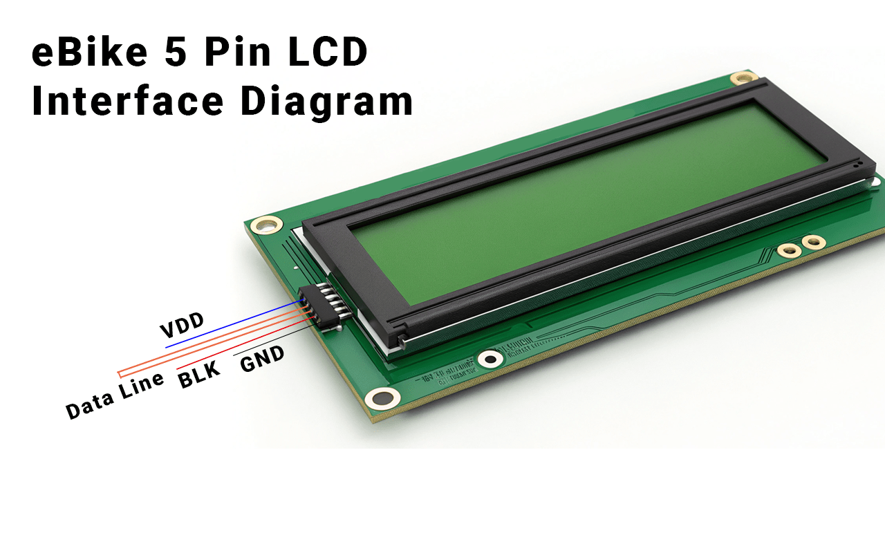
What is an eBike 5 Pin LCD Pinout?
The ebike 5 pin lcd pinout refers to the configuration of five pins connecting an LCD display to an eBike’s control system. These pins handle power, ground, data transmission, and backlight control, ensuring the display functions correctly and provides clear information to the rider.

What Are the Components of a 5 Pin LCD Connector?
A 5 pin lcd connector typically includes power (VCC), ground (GND), data (DATA), backlight positive (BL+), and backlight negative (BL-). Each pin plays a crucial role in powering the display and transmitting data for accurate information display.
What Are the Key Functions of the eDash 5 Pin LCD Connector Pinout?
The edash 5 pin lcd connector pinout consists of five main pins, each serving a specific function. These include power supply, ground, data transmission, and backlight control, all of which work together to ensure the LCD screen operates smoothly and displays information accurately.
How Do Power and Ground Pins Function?
The power (VCC) and ground (GND) pins supply the necessary electricity to the LCD screen. A stable power supply is essential for the display to function correctly and avoid flickering or shutdowns.
What Role Does the Data Pin Play?
The data (DATA) pin transmits information from the eBike’s controller to the LCD screen. This ensures that data such as speed, battery level, and other metrics are accurately displayed to the rider.
How is the Backlight Controlled?
Backlight positive (BL+) and backlight negative (BL-) pins manage the screen’s brightness. Proper backlight control enhances visibility in different lighting conditions and conserves battery life by adjusting brightness as needed.
How to Identify Each Pin in the eBike 5 Pin LCD Connector?
Identifying each pin in the ebike 5 pin lcd pinout involves consulting the data sheet and using a multimeter(What is a multimeter?) for verification. Typically, the pins are arranged in a standard order, but it’s essential to confirm each pin’s function to ensure proper connection.
How to Use the Data Sheet for Pin Identification
The data sheet(How to read an LCD data sheet) provides detailed diagrams and descriptions of each pin’s function. Comparing the data sheet with the physical connector helps in accurately identifying each pin’s role.
What Tools Are Needed for Pin Identification?
A multimeter is essential for measuring voltage and signals on each pin. This tool helps verify that each pin is correctly supplying power, ground, or data as specified in the data sheet.
How to Mark the Pins for Easy Identification
Once identified, use labels or colored tape to mark each pin. This practice prevents confusion during connections and makes future maintenance easier.
How to Properly Connect the eBike 5 Pin LCD to the Controller?
Properly connecting the ebike 5 pin lcd pinout to the controller involves a series of steps to ensure each pin is correctly linked. This process includes preparing tools, connecting power and ground, linking data and backlight pins, and testing the setup for functionality.
Step 1: Prepare Your Tools and Workspace
Ensure you have all necessary tools such as screwdrivers, a multimeter, and the appropriate cables. A clean and organized workspace helps prevent mistakes during the connection process.
Step 2: Connect Power and Ground Pins
Attach the VCC pin to the controller’s power output and the GND pin to the ground. Secure connections to avoid power fluctuations that could disrupt the LCD’s operation.
Step 3: Link the Data Pin
Connect the DATA pin from the LCD to the controller’s data input. This connection is vital for transmitting accurate information to the display.
Step 4: Attach Backlight Pins
Connect the BL+ and BL- pins to the controller’s backlight control. Adjust the brightness settings to balance visibility and power consumption.
Step 5: Test the Connection
After all connections are made, power on the system to check if the LCD displays correctly. If issues arise, recheck each connection to ensure accuracy and stability.
What Tools Are Needed to Replace the eDash Bike’s 5 Pin LCD Display?
Replacing the edash bike 5 pin LCD display requires specific tools to ensure a smooth and safe replacement process. Essential tools include screwdrivers, a multimeter, soldering tools(Best soldering tools for electronics), and a compatible replacement LCD module.
Essential Tool List
- Screwdrivers: For removing the bike’s casing and accessing the LCD connector.
- Multimeter: To verify pin connections and ensure correct voltage levels.
- Soldering Tools: Necessary for securing the new LCD module’s connections.
- Replacement LCD Module: Ensure it matches the specifications of the original display.
Step-by-Step Replacement Process
- Power Off the eBike: Disconnect the battery to prevent electrical accidents.
- Remove the Old LCD: Use screwdrivers to carefully detach the existing LCD from the bike’s frame.
- Identify the Pins: Refer to the edash 5 pin lcd connector pinout to understand each pin’s function.
- Connect the New LCD: Solder the new LCD’s pins to the corresponding controller pins, ensuring secure connections.
- Test the New Display: Reconnect the battery and power on the eBike to check the new LCD’s functionality.

What Are Common Issues with the eDash 5 Pin LCD Connector Pinout?
The edash 5 pin lcd connector pinout can encounter several common issues, such as the display not turning on, abnormal colors, or flickering. These problems typically stem from incorrect wiring, insufficient power supply, or signal interference.
Why Isn’t the Display Turning On?
A non-responsive display often results from power supply issues. Check the VCC and GND connections to ensure the LCD is receiving adequate power.
What Causes Abnormal Colors on the LCD?
Color anomalies can be due to faulty data transmission. Verify that the DATA pin is correctly connected and that there are no signal interruptions.
Why Does the LCD Flicker?
Flickering may occur from unstable backlight control or signal delays. Ensure the BL+ and BL- connections are secure and adjust the backlight settings if necessary.
How to Fix Wiring Errors
Double-check all connections against the edash 5 pin lcd connector pinout. Correct any miswired pins to restore proper functionality.
How to Optimize the eBike 5 Pin LCD’s Performance?
Optimizing the ebike 5 pin lcd pinout enhances display clarity and responsiveness. Techniques include adjusting backlight brightness, minimizing signal delays, and using high-quality cables to ensure stable data transmission.
How to Adjust Backlight Brightness
Fine-tuning the backlight can reduce power consumption while maintaining visibility. Use the backlight control pins (BL+ and BL-) to set the optimal brightness level for different lighting conditions.
How to Minimize Signal Delays
Using high-quality data cables and ensuring short, direct connections can reduce signal delays. This leads to faster display updates and a smoother user experience.
Why Use High-Quality Cables?
High-quality cables minimize signal loss and interference, ensuring that data is transmitted accurately and reliably. This results in clearer and more consistent display output.
How Regular Maintenance Helps
Regularly inspect and clean the LCD connectors to prevent dust and debris buildup. Secure connections ensure stable performance and reduce the likelihood of display issues.
Is the eBike 5 Pin LCD Pinout Compatible with 3.3V Microcontrollers?
The ebike 5 pin lcd pinout is generally compatible with both 3.3V and 5V microcontrollers, but it’s essential to verify the LCD module’s voltage requirements. Using voltage regulators(What is a voltage regulator?) or level shifters can ensure compatibility and protect the LCD from voltage mismatches.
How to Check LCD Module’s Voltage Requirements
Refer to the LCD module’s data sheet to determine its voltage requirements. Confirm whether it supports 3.3V, 5V, or both, ensuring compatibility with your microcontroller.
What Are Voltage Regulators and Their Importance?
Voltage regulators maintain a stable voltage level to the LCD, protecting it from voltage fluctuations. They ensure that the LCD receives the correct voltage, preventing damage and ensuring reliable operation.
How to Use Level Shifters for Signal Compatibility
Level shifters adjust the voltage levels of data signals between the microcontroller and the LCD. This ensures that data transmission is reliable and prevents signal degradation or miscommunication.
Conclusion and Recommendations
The ebike 5 pin lcd pinout is a fundamental component in eBike display systems, providing essential connections for power, data, and backlight control. By understanding its functions, correctly connecting each pin, and applying optimization techniques, you can ensure a reliable and high-performing LCD display. Referencing the edash bike example offers practical insights into real-world applications, enhancing your ability to install, replace, and maintain eBike LCD systems effectively.
Key Takeaways
- Understand the Pinout: Grasp each pin’s function in the ebike 5 pin lcd pinout.
- Accurate Connections: Ensure each pin is correctly connected to prevent display issues.
- Troubleshoot Effectively: Identify and resolve common problems swiftly using proper tools.
- Optimize Performance: Implement advanced techniques to enhance display clarity and responsiveness.
- Ensure Compatibility: Verify voltage requirements and use appropriate regulators or level shifters.
Recommended Resources
- Data Sheets: Access detailed specifications for different LCD modules.
- Toolkits: Invest in quality tools like multimeters and soldering kits for precise connections.
- Online Tutorials: Utilize video guides and forums for additional support and tips.
- Quality Components: Purchase reliable connectors and cables to ensure long-term performance.
By following this comprehensive guide, you can effectively manage the ebike 5 pin lcd pinout, ensuring your eBike’s display system is both functional and optimized for the best riding experience.