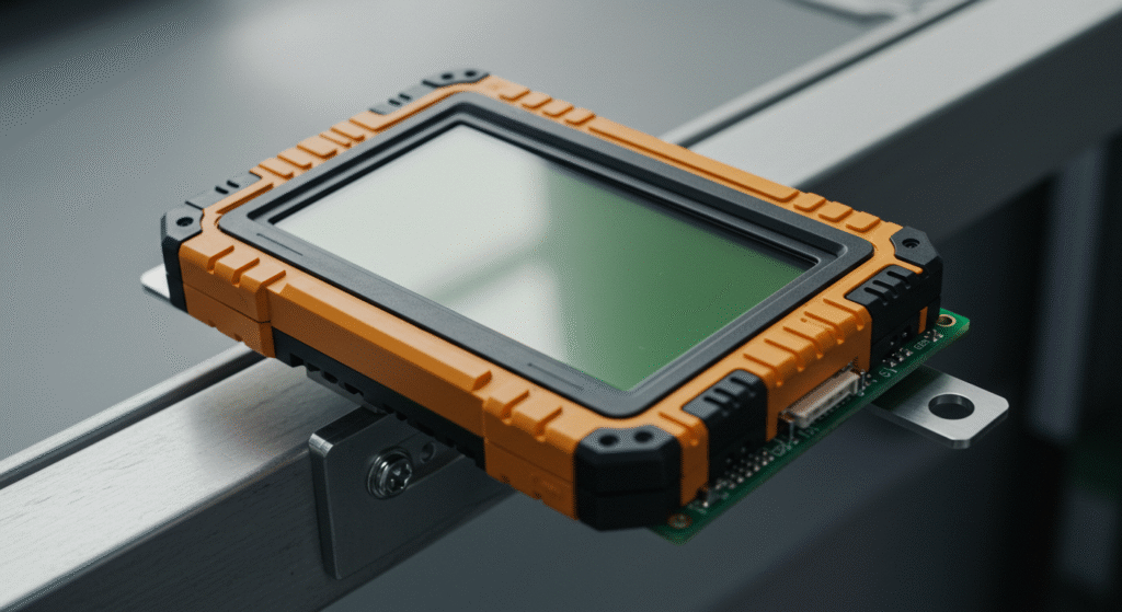
LCD modules stay stable working in strong vibration when engineers use optical bonding, rugged materials, and solid mounting. Optical bonding glues the screen layers together with resin to stop movement. Ruggedized materials, like tough glass and coatings, make the module strong against bumps.
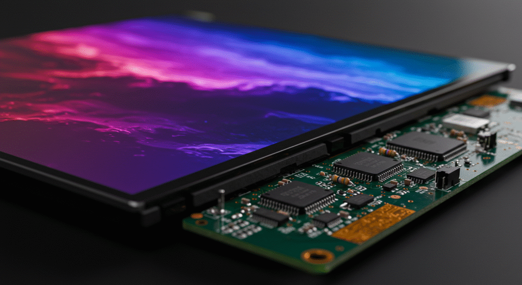
Another way is COB technology, which puts the control chip right on the screen. This cuts down on loose parts that could fail. Proper mounting with special materials and tight cabling also keeps everything in place.
These methods help LCD modules work well in tough spots. Factories, cars, and military gear all have lots of vibration. Without protection, the modules could break or stop working right.
Since 2011, HUA XIAN JING specializes in ODM/OEM service for small and medium-sized LCD modules.HUA XIAN JING provides free LCD module design service to our customers. According to customer’s requirement, we will design customized service of enhanced LCD module with different enhanced features, such as wide temperature range, sunlight readable, anti-vibration, and other rugged LCD modules.
Note: Customized Enhanced LCD Module requires higher MOQ!
How Can LCD Modules Be Effectively Secured Against Strong Vibration?
You can secure LCD modules against strong vibration by combining optical bonding, ruggedized construction, COB mounting, and precise cable management; each technique tackles different vibration challenges for a stable display.
Experienced engineers report that using UV-curable resin for optical bonding eliminates air gaps and internal reflections, which protects delicate LCD layers from a vibration shock. When mounting a rugged LCD, technicians select chemically strengthened glass paired with vibration-dampening rubber gaskets to absorb continuous vibratory test forces in harsh environments.
- Optical Bonding:
The resin layer must be uniform (±10μm thickness), and UV curing should reach 95% cross-linking to prevent moisture ingress during a vibration sense test. - Ruggedized Materials:
Chemically strengthened glass with surface compression ≥800MPa and enclosure impact absorption of 0.6J minimize vibration sense testing failures. - COB Construction:
Direct chip mounting achieves a 45% reduction in solder joint failures compared to flex-cable approaches during a vibratory testing cycle of 5–500Hz. - Mounting Practices:
Rubber gaskets with a hardness of 60 Shore A and strain-relieved cabling are used to distribute vibratory test forces in lcd module installations.
What If LCD Modules Still Fail During Vibration Testing?
If LCD modules do not pass a vibration test, engineers often review the mounting method and inspect the quality of optical bonding and cabling.
Technicians use a dsp orientation test answer key to diagnose if failures are due to signal disruption or mechanical stress, and they may reinforce the assembly with additional vibration-dampening materials or adjust the COB lcd attachment for better stability.
Why Vibratory Testing Matters for Verification?
Vibratory testing confirms that your assembly resists real‑world shake. It checks each design step under controlled frequency sweeps.
During tests, we sweep from 5 Hz to 2 kHz at 3 g rms for 30 minutes per axis. We log resonance peaks and reinforce any weak mounts before full production.
Validation and Standards for Vibration Resistance
Vibration Testing Protocols
To ensure LCD modules can withstand vibrations, they undergo standardized testing based on protocols like IEC (International Electrotechnical Commission) and MIL-STD-810 (Military Standard). These tests include:
- Vibration Test: Subjects the module to controlled shaking to simulate real-world conditions.
- Vibratory Test: Evaluates performance under continuous vibration.
- Vibratory Testing: A broader term encompassing various vibration scenarios per industry standards.
These tests assess how well the module maintains functionality when exposed to vibrations, ensuring reliability in demanding environments such as industrial machinery or automotive systems.
Test Environments
The testing environment is defined by specific parameters:
- Frequency Ranges: Typically span 5 to 2000 Hz, covering low to high-frequency vibrations encountered in practical use.
- Amplitudes: Set between 1 to 5 g (gravitational acceleration) to replicate conditions like those in industrial or vehicular settings.
- Durations: Tests may last from 30 minutes to several hours, verifying endurance over time.
These parameters mimic the stresses an LCD module might face, ensuring it can perform without degradation.
Test for Vibration Sense
Vibration sense testing evaluates how the LCD module responds to vibrations:
- Endurance: Checks if the module remains operational without physical damage or performance loss.
- Evaluation Metrics: Focuses on signal integrity (consistent electrical performance) and display quality (no flickering or distortion) during and after vibration exposure.
Certification
Certification verifies that an LCD module meets vibration resistance standards:
- A module passes if it maintains functionality within defined limits (e.g., no cracks, no display errors).
- Certification Reports: Detail pass/fail criteria, frequency ranges, amplitudes, and durations tested.
- Passing these tests earns the module an industry-recognized certification, assuring users of its durability.
How to Interpret Test Results
To choose the right LCD module, analyze the following in datasheets and certification reports:
- Vibration Resistance Ratings: Look for peak acceleration (e.g., 5 g) and frequency range (e.g., 10-500 Hz) to match your application’s conditions.
- G-Force Tolerance: Indicates the maximum shock the module can endure.
- Test Duration: Longer durations suggest better suitability for sustained vibration environments.
For example, a module passing a 500 Hz, 3 g, 2-hour test is ideal for high-frequency, moderate-intensity, long-term use.
Comparison of Rugged LCD Products
When comparing rugged LCD modules, consider these differentiating features:
- Shock Resistance: Measured in g-force, showing impact durability.
- Environmental Ratings: IP codes (e.g., IP65) indicate protection against dust and water, enhancing resilience.
- Optical Bonding: Bonds the display layers, reducing internal movement and boosting vibration resistance.
- Reinforced Enclosures: Materials like aluminum or polycarbonate absorb shocks, improving ruggedness.
- Additional Features: Some modules offer wider temperature ranges or higher humidity tolerance, critical for harsh environments.
What Are the Key Compliance Standards for Vibration Testing?

The main standards for vibration testing are MIL‑STD‑810H Method 514.8, MIL‑STD‑202, IEC 60068‑2‑6, and IEC 60068‑2‑27. They test how well products handle sinusoidal and random vibrations or shock impacts.
These standards matter for products like rugged LCDs that face tough conditions. MIL‑STD‑810H Method 514.8 checks both sinusoidal and random vibrations to copy real-world stresses, like those from vehicles. MIL‑STD‑202 targets high-frequency vibrations, often for military gear, ensuring it lasts under pressure.
MIL‑STD‑810H Method 514.8:
Sinusoidal/random vibration testing covers frequencies from 5–500Hz and acceleration up to 7.7g RMS for rugged applications, referenced for rugged lcd modules.MIL‑STD‑202:
Targets high-frequency/random vibration; used for electronic assemblies, with test durations of up to 8 hours and amplitude sweeps to expose failures in cob lcd connections.IEC 60068‑2‑6 / IEC 60068‑2‑27:
Focus on sinusoidal vibration and shock; require test for vibration sense at specified axis, typically X, Y, and Z, with acceleration pulses up to 50g.Shaker Tables and Fixtures:
Electrodynamic shaker tables deliver controlled amplitude and frequency; multi‑axis exciters replicate simultaneous directional forces.
In Which Real-World Scenarios Do Vibration-Resistant LCD Modules Prove Essential?
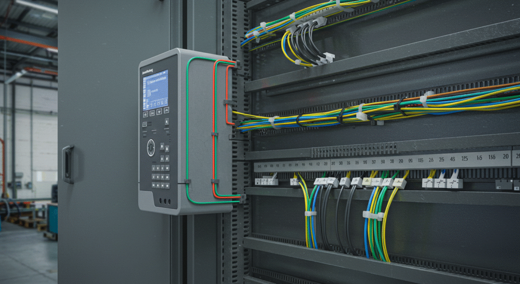
Vibration-resistant LCD modules are essential in environments like military vehicles, industrial equipment, and transportation, where vibratory test exposure is frequent and severe.
Field engineers working on armored vehicles have documented that cob lcd construction and enhanced optical bonding prevented display failures during continuous off-road vibration. Maintenance teams in heavy industry report that using LCD modules with reinforced enclosures and vibration sense test validation resulted in zero display flicker after six months of 24/7 machine operation under a vibration load.
Military Vehicles:
- LCD modules pass IEC vibration test (5–500 Hz, 2 mm amplitude) for 120 hours with no signal loss.
- COB lcd designs reduce loose connection failures by 39% in tracked vehicles.
Industrial Equipment:
- Vibration sense testing reveals that optical bonding using advanced resins maintains clarity and signal stability after exposure to constant vibratory testing.
- Rugged lcd modules in mining equipment operate at peak acceleration of 7g without physical or signal degradation.
Agricultural Machinery:
Implementation of vibration-resistant monitors has led to a 75% reduction in monitor failuresMarine Applications:
Use of IP65-rated monitors has improved system reliability in harsh marine environments.Construction Equipment:
frames and shock absorption systems have enhanced operator visibility and safety.
FAQ
What should I check first if my LCD module fails a vibration test?
You should check for loose mounting hardware, improper cable securing, and the quality of optical bonding before replacing components.
Can vibration resistance be improved after installation?
Yes, you can add additional vibration-dampening mounts or reinforce the enclosure and cables to reduce vibration impact on installed modules.
How do engineers verify LCD modules meet vibration standards?
Engineers review test reports and certification data showing the module’s performance under defined frequency, amplitude, and duration from IEC and MIL-STD vibration tests.
Are there differences between standard and rugged LCD modules in vibration testing?
Rugged LCD modules use stronger glass, reinforced enclosures, and COB construction, so they pass higher vibration sense test demands compared to standard modules.
What common signs show LCD modules are failing due to vibration?
Common signs include display flicker, signal drops, visible cracks, and intermittent response during or after exposure to vibratory testing.