Page addressing mode keeps the column pointer inside one page, so the controller does not move to the next page unless you send a new command. Horizontal addressing mode lets the controller move from one page to the next without extra commands, which helps when you want to send a lot of display data in a row.
These addressing modes show up in many display controllers for medium and small LCD modules, especially in IoT devices and wearables. Picking the right addressing model can change how fast and easy it is to update what you see on the screen.
Addressing modes are a basic idea in computer architecture, and they shape how microcontrollers and software handle display memory. Understanding these methods helps developers get the most out of their hardware and avoid common display bugs.
What are the main differences between page addressing mode and horizontal addressing mode?
Page addressing mode restricts pointer movement within one page, while horizontal addressing mode allows the pointer to move across pages automatically. These modes serve different update needs for embedded LCD modules.
In production, engineers working with embedded LCD systems use page addressing mode for precise, manual control over memory writes, especially when only static icons or text need updates. Horizontal addressing mode is chosen for efficient streaming of full-screen graphics or animations, where automated pointer progression across multiple pages is needed. By configuring the addressing model through specific controller commands, developers can match display update requirements to the right addressing type for both performance and memory efficiency.
- Page Addressing:
- Pointer stays within the same page; column pointer auto-increments, wraps around at the end; page pointer stays fixed.
- Manual commands required to advance to a new page.
- On many controllers, mode bits (for example, A[1:0]=10b) define this addressing method.
- Horizontal Addressing:
- Pointer auto-increments both the column and then, at the end, page pointer as well.
- Minimal intervention needed from the host; suits continuous data streams.
- Set via controller-specific commands (like A[1:0]=00b for SSD1306).
Key parameters:
- Addressing modes are set via the “Set Memory Addressing Mode” command (often 0x20).
- Horizontal addressing mode automates vertical progression, so engineers rarely need to adjust the page pointer manually, saving code space and update cycles.
What is the impact of addressing mode selection on embedded LCD update efficiency?
The choice between page and horizontal addressing modes directly affects how efficiently data can be written to the display.
Page addressing mode may cause increased command overhead when updating large areas, because each page change needs a new command. Horizontal addressing mode reduces CPU intervention, enabling faster, uninterrupted bulk writes when updating multiple pages in sequence.
- Page addressing: Best for updating small, discrete regions; less optimal for full-screen changes.
- Horizontal addressing: Enables block transfers for graphics and animations; reduces the number of addressing commands per frame.
- Addressing modes set the memory access pattern for LCD modules in embedded systems, which can affect both refresh rate and power usage.
- For medium and small LCD modules, correct addressing type selection leads to smooth visual output and responsive interfaces.
How does pointer flow differ between page addressing mode and horizontal addressing mode?
In page addressing mode, the page pointer remains fixed while the column pointer auto-increments within a single page; in horizontal addressing mode, both the column pointer and page pointer progress automatically as data is written. The behavior can confuse new developers working with embedded LCD modules.
When beginners start with display controllers, they often mistake the static page pointer in page addressing mode for an error when their writes appear to “stop” at a page boundary. Horizontal addressing mode eliminates this issue by moving the page pointer forward automatically, so data fills the entire memory block without manual intervention. To avoid this confusion, always consult the addressing model diagrams in the controller datasheet and trace both pointer behaviors side by side. The calculation of the effective address—the actual memory location being written—depends on the addressing mode and must be understood to avoid unexpected display artifacts.
Page Addressing Mode Example:
					// Set page address to 2, column address to 10
set_page_address(2);
set_column_address(10);

// Write 8 bytes to the current page
for (int i = 0; i < 8; i++) {
    write_data(buffer[i]); // COL increments from 10 to 17, PAGE stays at 2
}
// At COL=127, next write wraps COL to 0, PAGE remains at 2
Horizontal Addressing Mode Example:
					// Set page address to 2, column address to 10
set_page_address(2);
set_column_address(10);

// Write 160 bytes (crossing pages)
for (int i = 0; i < 160; i++) {
    write_data(buffer[i]);
    // COL increments from 10 to 127, then wraps to 0 and PAGE increments to 3
    // Continues automatically through following pages
}
Key Visual Reference:
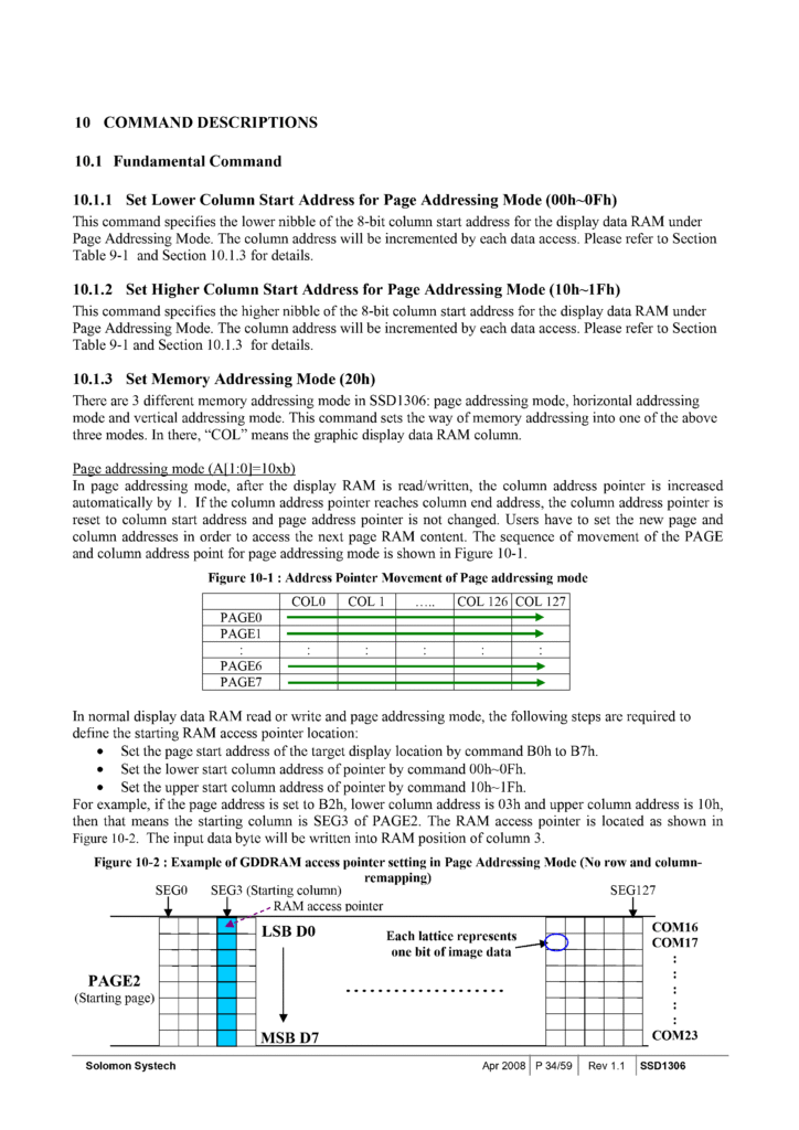
- SSD1306 Figure 10-1: Shows how COL pointer wraps in page mode, but PAGE is static.
- SSD1306 Figure 10-3: Illustrates both COL and PAGE pointers moving in horizontal mode.
Effective address calculation:
- In page mode:
address = PAGE * PAGE_WIDTH + COL - In horizontal mode: Controller auto-increments both, so a continuous stream fills the memory row by row.
Why do display artifacts occur when using the wrong addressing mode?
Display artifacts happen because data is written to unintended memory locations when the addressing mode does not match the data pattern.
If a developer writes a long data stream in page addressing mode, only part of the screen updates, and the rest may overwrite the same page repeatedly. Using horizontal addressing mode for line-by-line updates prevents this, as the memory pointers advance correctly and fill the entire display area as intended.
- Mismatch in addressing methods often causes overwriting or gaps on the display.
- Effective address mismatches show up as repeated rows or missing sections, especially on medium and small LCD modules.
- Referring to addressing model figures in datasheets and matching the addressing type to the data layout is essential for clear display output.
- Novice developers should always check both the addressing mode setting and the sequence of pointer progression to avoid unexpected visual output.
How can developers handle hardware-specific quirks in page and horizontal addressing modes?

Hardware quirks such as pointer misalignments in page mode or page pointer failures in horizontal mode often appear on displays with different resolutions or controller revisions. Developers must use thorough testing, verify RAM boundaries, and consult errata documentation to prevent unexpected blank areas or misaligned updates.
Different embedded LCD modules (for example, 128×32 versus 128×64) can have undocumented differences in their addressing model implementation. Some controllers may, in page addressing mode, misreport the effective address at certain page boundaries, causing data to appear in the wrong location. In horizontal addressing mode, rare controller bugs may stop the page pointer from auto-incrementing, leaving parts of the display blank. To avoid these pitfalls, engineers should always read the datasheet closely, check for module-specific addressing model errata, and programmatically test all RAM regions after initialization to ensure the addressing mode behaves as expected.
Detecting and Mitigating Addressing Mode Bugs
Testing RAM Boundaries:
					// Fill all display RAM with a test pattern, then read back if possible
for (int page = 0; page < NUM_PAGES; page++) {
    set_page_address(page);
    set_column_address(0);
    for (int col = 0; col < NUM_COLS; col++) {
        write_data(0xAA); // Known pattern
    }
}

// Visually inspect or read back if supported
// Look for missing, blank, or misaligned segments on the LCD
Error-Handling Strategy:
- Check module errata for notes on addressing types and pointer anomalies.
- Use test patterns to validate that the addressing model updates the correct regions.
- Reconfigure addressing mode if anomalies are observed, or consider a manual addressing workaround.
Key technical data:
- On some 128×32 displays, page mode may not map all columns to visible pixels, causing partial updates.
- With certain controller versions, horizontal mode may skip a page, leaving a horizontal line blank.
- Addressing mode bugs can sometimes be traced to incorrect RAM mapping or controller silicon revisions.
What should developers do if addressing mode bugs persist despite configuration changes?
Developers can implement manual pointer control and use custom update routines to bypass controller bugs.
When the addressing model does not perform as documented, direct control over column and page pointers using manual addressing commands can help ensure all memory regions update correctly. This approach trades automation for reliability where hardware quirks exist.
- Manual addressing means explicitly setting both page and column addresses before each data write, regardless of the current addressing mode.
- This approach helps when automatic pointer increment fails, especially in embedded LCD systems with known issues.
- Testing every addressable pixel ensures full coverage and helps identify non-obvious addressing method bugs.
- For medium and small LCD modules, this strategy guarantees consistent display output even when the addressing model implementation is not standard.
What are the practical steps to implement page and horizontal addressing modes with code examples?

To use page addressing mode, you set the page address, specify the column range, and write data page by page. In horizontal addressing mode, you set a starting address and write data continuously, letting the controller automatically handle page transitions.
When working with embedded LCD modules using microcontrollers like STM32 or ESP32, you must send specific addressing model commands over SPI or I²C. For page addressing, each page is updated individually, which requires careful management of page and column pointers. For horizontal addressing, you can send a long buffer, and the controller increments the page pointer automatically. The most common errors happen when developers misindex the starting address or miscalculate buffer lengths, which leads to addressing mode pointer errors or display artifacts.
Code Examples for Addressing Modes
Page Addressing Mode (SPI/I²C for STM32/ESP32):
					// Example: Update one page (y=2) from column 0 to 127
set_addressing_mode(PAGE_MODE); // Send command 0x20, A[1:0]=10b
set_page_address(2);            // Send command 0xB2 for PAGE=2
set_column_address(0);          // Send column start address, e.g., 0x00

for (int col = 0; col < 128; col++) {
    write_data(buffer[col]);    // Write 128 bytes, one page
}
// Repeat for each page as needed
Horizontal Addressing Mode (SPI/I²C for STM32/ESP32):
					// Example: Update entire display (multiple pages) from column 0, page 0
set_addressing_mode(HORIZONTAL_MODE); // Send command 0x20, A[1:0]=00b
set_page_address(0);                  // Start at page 0
set_column_address(0);                // Start at column 0

for (int i = 0; i < TOTAL_DISPLAY_BYTES; i++) {
    write_data(framebuffer[i]);       // Write entire buffer, controller auto-increments
}
Open-source Library Example (U8g2/Adafruit SSD1306):
					// Pseudo-code using Adafruit SSD1306 library for horizontal mode
display.begin();
display.setMemoryMode(SSD1306_HORIZONTAL_MODE); // Custom function or use begin()
display.clearDisplay();
display.drawBitmap(0, 0, bitmap, WIDTH, HEIGHT);
display.display(); // Writes buffer in horizontal addressing mode
Key technical tips:
- Always check the memory boundaries: for a 128×64 LCD, there are 8 pages (each 8 pixels tall), 128 columns.
- Address index errors are common; verify your buffer size matches your display RAM.
- Use library initialization calls to set the correct addressing model before writing data.
How can developers avoid pointer indexing mistakes during implementation?
Developers can use explicit checks and buffer validation routines to ensure data aligns perfectly with the display’s memory map.
Before writing to the display, always confirm that the buffer length matches the expected number of columns per page (for page mode) or the total display RAM (for horizontal mode). Implementing boundary checks and validating data offsets prevents addressing mode bugs that might cause missing rows or columns.
- Page addressing:
buffer size per page = number of columns(e.g., 128 bytes per page for a 128×64 display). - Horizontal addressing:
buffer size = total pages × columns(e.g., 8 pages × 128 columns = 1024 bytes for 128×64). - Indexing errors often result in partial updates or display glitches; always check your effective address calculations before writing data.
- Use debugging output or test patterns to verify correct display updates after each command sequence.
What alternative addressing modes exist, and how do they affect data writing patterns?
Vertical addressing mode increments the page pointer first and then the column pointer, making it ideal for column-wise data updates. The wrapping behavior of pointers, controlled by configurable start and end addresses, determines where data flows and how it wraps around in the display memory.
For embedded LCD modules, vertical addressing mode provides a different data flow compared to page or horizontal addressing modes. When this addressing model is enabled, writing data will fill memory down a column before moving to the next column, which benefits applications such as vertical graphs or column-major text rendering. Developers must carefully set the start and end addresses for both pages and columns to control how and where the pointer wraps. This addressing type is rarely the default and may require explicit controller commands. Understanding this behavior allows engineers to match the addressing method to their data pattern for more efficient updates and fewer artifacts.
Vertical Addressing Mode and Pointer Wrapping
Vertical Addressing Mode (Pseudo-Code for Generic Controller):
					// Set vertical addressing mode (typically A[1:0]=01b)
set_addressing_mode(VERTICAL_MODE); // Send command 0x20, A[1:0]=01b
set_column_address(COLUMN_START);   // Set initial column
set_page_address(PAGE_START);       // Set initial page

for (int col = COLUMN_START; col <= COLUMN_END; col++) {
    set_column_address(col);
    for (int page = PAGE_START; page <= PAGE_END; page++) {
        set_page_address(page);
        write_data(columnBuffer[page]);
        // PAGE increments first, then COLUMN
    }
    // At PAGE_END, PAGE wraps to PAGE_START and COLUMN increments
}
Pointer Wrapping Behavior:
- Start/End addresses for columns and pages are set using controller commands (example:
set_column_address,set_page_address). - When the page pointer reaches PAGE_END, it wraps to PAGE_START and the column pointer increments.
- Proper configuration ensures that memory writes do not overwrite unintended areas, especially in medium and small LCD modules.
Key Points:
- Vertical addressing is optimal for column-major data but requires careful address index management.
- Misconfigured wrapping can cause overwrites or blank segments on the display.
When should developers choose vertical addressing mode over other addressing methods?
Vertical addressing mode is best used in applications where data naturally fills columns before rows or for effects that animate vertically rather than horizontally.
For example, vertical bar graphs, waterfall charts, or column-based scrolling displays benefit from this addressing method because it matches the data’s structure and reduces pointer management overhead. Choosing the correct mode streamlines updates and ensures consistent data placement.
- Vertical addressing is typically less common but is supported on many controllers, including those for embedded LCD systems.
- Applications that require fast updates to single columns or column groups see performance gains using vertical mode.
- If the addressing model does not match the application’s data pattern, it can lead to inefficient memory writes or visual glitches.
- Always verify effective address mapping and test output visually after enabling vertical mode.
How can developers optimize performance and buffer management for different addressing modes?
DMA enables fast, large data transfers in horizontal addressing mode, while manual writes are practical for small, discrete updates in page addressing mode. Buffer sizing must align with the chosen addressing model to balance speed and memory usage in embedded LCD systems.
In embedded development, using DMA with horizontal addressing mode allows developers to move entire screen buffers with minimal CPU intervention, maximizing throughput for animations or full-screen refreshes. For page addressing mode, smaller, page-sized buffers fit well with manual data writes, conserving RAM and simplifying pointer management. Choosing the correct addressing type based on the application’s update pattern helps avoid unnecessary memory allocation or underutilized bandwidth. Engineers should benchmark both approaches, considering the impact on system responsiveness and memory footprint, especially in medium and small LCD modules.
Buffer Management and Data Transfer Methods
DMA Transfer in Horizontal Addressing Mode:
					// Configure DMA for SPI transfer
set_addressing_mode(HORIZONTAL_MODE); // 0x20, A[1:0]=00b
set_page_address(0);
set_column_address(0);

HAL_SPI_Transmit_DMA(&hspi, framebuffer, DISPLAY_WIDTH * DISPLAY_PAGES);
// Example: 128x64 LCD = 128 columns x 8 pages = 1024 bytes
Manual Writes in Page Addressing Mode:
					set_addressing_mode(PAGE_MODE); // 0x20, A[1:0]=10b

for (int page = 0; page < DISPLAY_PAGES; page++) {
    set_page_address(page);
    set_column_address(0);
    for (int col = 0; col < DISPLAY_WIDTH; col++) {
        write_data(pageBuffer[page][col]); // Buffer only for one page at a time
    }
}
Buffer Sizing Comparison Table:
| Addressing Mode | Buffer Size Required | Use Case |
|---|---|---|
| Page Addressing | DISPLAY_WIDTH bytes (per page) | Static icons, text rows |
| Horizontal Addressing | DISPLAY_WIDTH × PAGES bytes | Full-screen graphics, animation |
Key technical notes:
- DMA setup requires buffer alignment and must match the controller’s addressing mode.
- Manual writes use less RAM but increase CPU overhead for each update.
- Buffer index errors can cause addressing mode artifacts; always validate size and alignment.
How does buffer management impact speed and memory usage in embedded LCD systems?
Large buffers enable faster bulk transfers but consume more RAM, while smaller page buffers reduce memory use at the cost of slower updates.
In systems with limited RAM, developers may prefer page mode with manual updates to minimize memory footprint. In performance-critical designs, using a full-screen buffer with DMA in horizontal mode can drastically improve display refresh rates but requires careful memory planning.
- DMA can operate in background, freeing CPU for other tasks.
- Manual writes are easier to debug and can target specific regions with minimal overhead.
- For medium and small LCD modules, always check for controller-specific DMA support and buffer size limitations.
- Monitor both transfer speed and RAM usage to avoid unexpected slowdowns or out-of-memory errors.
How can addressing modes be integrated with microcontrollers and graphics libraries?
Microcontrollers like STM32, ESP32, or AVR configure addressing modes using direct or indexed addressing in firmware to manage display writes. High-level graphics libraries (such as LittlevGL or TFT_eSPI) often abstract these addressing methods, making it easier to work with both page and horizontal addressing modes.
When integrating embedded LCD modules, developers set the addressing model by sending specific commands from their microcontroller code, either through direct register control or via indexed loops for bulk data writes. Microcontrollers support both direct addressing (manually setting each page and column) and indexed addressing (using pointers or counters to automate updates). Graphics libraries simplify this process with APIs that internally select the correct addressing type and handle buffer management, reducing the risk of addressing mode errors and pointer misalignment. Checking the library’s documentation and source ensures support for the targeted display and addressing mode.
Addressing Modes with Microcontroller Code and Libraries
STM32: Manual Addressing Control (Page Mode Example)
					// Set page addressing mode (SSD1306 example)
set_addressing_mode(PAGE_MODE); // Command 0x20, A[1:0]=10b

for (int page = 0; page < DISPLAY_PAGES; page++) {
    set_page_address(page);
    set_column_address(0);
    for (int col = 0; col < DISPLAY_WIDTH; col++) {
        write_data(displayBuffer[page][col]);
    }
}
ESP32: Indexed Addressing for Horizontal Mode
					set_addressing_mode(HORIZONTAL_MODE); // Command 0x20, A[1:0]=00b
set_page_address(0);
set_column_address(0);

for (int i = 0; i < DISPLAY_WIDTH * DISPLAY_PAGES; i++) {
    write_data(framebuffer[i]); // Indexed buffer for automatic pointer management
}
Graphics Library Example (LittlevGL/lvgl)
					// LVGL handles addressing internally
lv_obj_t *scr = lv_scr_act();
lv_obj_t *label = lv_label_create(scr);
lv_label_set_text(label, "Hello LCD!");

// Library ensures correct addressing mode for the hardware driver
Key technical points:
- Microcontroller firmware can use direct addressing for precise control or indexed addressing for streamlined updates.
- Graphics libraries like LittlevGL or TFT_eSPI provide high-level APIs that abstract away low-level addressing details.
- Always verify that the library and hardware driver support both page and horizontal addressing modes for your display.
What should developers check when using graphics libraries with different addressing modes?
Developers must confirm that their chosen graphics library fully supports the display’s addressing model, including both page and horizontal addressing.
Some libraries default to one addressing mode and may require driver configuration or patches to switch modes. Reviewing the library’s initialization routines and ensuring compatibility with the target LCD module prevents addressing type mismatches and display artifacts.
- Open-source libraries often contain driver files where addressing mode can be set at initialization.
- For custom displays or rare modes (like vertical addressing), developers might need to extend or modify the driver.
- Always test display updates with test patterns to confirm the addressing model is correctly handled by the library and microcontroller together.
FAQ
What happens if I mix addressing modes during display updates?
Mixing addressing modes without resetting the pointers often causes unpredictable display artifacts or memory misalignment, so always reinitialize the addressing mode before sending new data.
Can I use both page and horizontal addressing in the same project for different tasks?
Yes, you can switch between modes as needed, but make sure to set the correct addressing mode command each time before sending data to the display.
How do I know which addressing mode my LCD controller supports?
Check the controller’s datasheet for a section labeled “addressing modes” or “memory addressing,” and look for supported commands and recommended modes for your display size.
What should I do if my data appears shifted or mirrored on the LCD?
Check your starting page and column addresses, confirm the addressing mode, and review buffer alignment to ensure your data maps correctly to the display memory.
Are addressing mode commands the same across all controllers?
No, commands and bit patterns often differ between controller models, so always consult your hardware documentation before sending addressing mode configuration bytes.