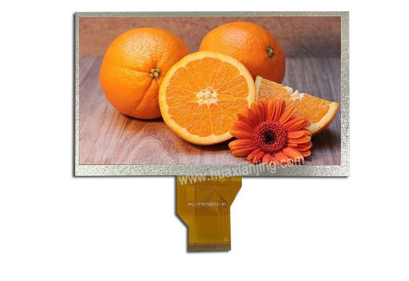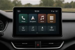
In automotive systems, a microcontroller handles CAN or LIN bus integration with LCD modules by acting as a bus node. It connects to a CAN or LIN transceiver to receive data, processes it, and updates an LCD module—like a TFT LCD or automotive screen—to show real-time details such as sensor readings or navigation info.
CAN networks deliver fast and reliable communication for complex tasks, while LIN buses provide a simple and affordable option for basic functions. Both send data to LCD displays, allowing drivers and passengers to interact with the vehicle’s systems easily.
This article will cover the hardware and software used in this process, the challenges that come up, and advanced ideas for making CAN or LIN communication with LCD modules work smoothly.
What Are the Key Differences Between CAN and LIN Bus Physical Layer Interfaces?
CAN and LIN buses differ in their physical layer interfaces: CAN uses a differential two-wire setup for speeds up to 1 Mbit/s, while LIN relies on a single-wire design with a rate of about 20 Kbaud. These differences shape their roles in automotive systems, with CAN handling fast, critical tasks and LIN supporting simpler, cost-effective ones.
From an industry perspective, CAN’s two-wire design offers strong resistance to noise, which suits it for complex systems like engine controls. On the other hand, LIN’s single-wire approach cuts down on wiring costs and complexity, making it a go-to for basic functions like window controls.
Topology:
- CAN: Uses a differential two-wire topology. This setup boosts noise resistance and supports higher speeds.
- LIN: Relies on a single-wire topology. It’s simpler but less robust against interference.
Data Rates:
- CAN: Reaches up to 1 Mbit/s, fitting for time-sensitive automotive tasks.
- LIN: Runs at around 20 Kbaud, enough for less urgent applications.
Transceiver Selection:
- LIN Transceivers: Include wake-inhibit and fault protection features, tailored for single-wire use in a lin network.
- CAN Transceivers: Need compatibility with a differential bus, wide common-mode range, and error protection for can networks.
Bus Topology Considerations:
- Termination: CAN requires resistors at the ends to stop signal bounce, while LIN’s single wire needs less effort.
- Stub-Length: CAN demands short stubs to keep signals clear, but LIN tolerates longer ones due to its slower speed.
- EMI/Protection: Both need shielding from interference, though CAN’s higher speed calls for extra care in automotive lin bus setups.
How Do Wiring and Protection Needs Differ for CAN and LIN Buses?
CAN bus wiring focuses on maintaining signal quality with twisted pairs and termination, while LIN bus wiring prioritizes simplicity and fault protection with its single-wire design. These approaches affect how each fits into a vehicle’s can/lin communication network.
Wiring Strategies:
- CAN: Uses twisted pair cables to cut noise, following strict rules for stubs and termination in can bus vs lin bus designs.
- LIN: Sticks to a single wire, keeping costs low but needing solid grounding for stability.
Protection Mechanisms:
- CAN: Adds tools like chokes and ESD guards to handle noise and spikes in can network interface systems.
- LIN: Relies on overcurrent and heat protection to survive tough conditions in a lin local interconnect network.
Implementation Notes:
- CAN: Suits critical systems with backup wiring for reliability.
- LIN: Works for basic tasks, offering a cheaper setup in automotive lin bus applications.
What Are the Key Considerations for Integrating a Microcontroller with CAN/LIN Buses and an LCD Module in Automotive Applications?

To integrate a microcontroller with CAN/LIN buses and an LCD module, you must select the right peripherals for communication, ensure voltage and timing compatibility, and choose an appropriate LCD interface. These steps are critical for reliable operation in automotive systems. From an industry perspective, a dedicated CAN controller can handle complex networks more efficiently than a UART for LIN, while SPI or I²C interfaces for LCDs save pins but may limit speed compared to parallel options, which suit graphic displays better.
Peripheral Support:
- CAN: A dedicated CAN controller manages the protocol directly, reducing the microcontroller’s workload in can networks.
- LIN: Using a Serial Communication Interface (SCI) or UART works well for LIN, offering a cost-effective solution for simpler tasks in a lin network.
- LCD Interface: Options like GPIO, SPI, I²C, or parallel ports connect to an embedded LCD module, with SPI and I²C being popular for small and medium size lcd displays due to their low pin requirements.
Voltage-Level & Timing Matching:
- Logic-Level Translation: Voltage differences between the microcontroller, bus transceivers, and LCD module often require level shifters to ensure compatibility.
- Timing Budgets: Clock speeds and data rates must align across the MCU, communication buses, and LCD module to prevent delays or data corruption.
LCD Module Interface:
- Display Types: Character LCDs are ideal for basic text, while tft lcd displays provide detailed graphics for automotive lcd screen applications.
- Controllers: Modules with onboard controllers simplify integration, whereas raw panels paired with external controllers offer more design flexibility.
- Interfaces: SPI and I²C are compact but slower, suitable for smaller displays; 8/16/24-bit parallel and LVDS deliver faster data transfer for larger, high-performance screens.
What Are the Key Considerations for Selecting LCD Display Types and Controllers?
Choosing an LCD interface means balancing speed, pin count, and complexity, especially in the tight spaces of automotive designs. This choice directly affects performance and ease of integration.
Interface Trade-Offs:
- SPI/I²C: These use fewer pins but cap data speed, fitting well with small and medium size lcd setups.
- Parallel: Offers higher speed at the cost of more pins, ideal for larger tft lcd displays.
- LVDS: Provides fast data transfer and low electromagnetic interference, often seen in advanced automotive lcd screen systems, though it demands specific hardware.
Common Pitfalls:
- Timing Issues: Unmatched clock speeds can lead to display lag or flickering.
- Voltage Mismatch: Incorrect voltage levels risk component damage or signal errors.
Best Practices:
- Interface Selection: Pick an interface based on the display’s data needs and the microcontroller’s pin availability.
- Testing: Check timing and voltage compatibility early to catch issues before they escalate in embedded LCD module designs.
System-Level Design Considerations for Automotive Communication and Display Systems
Designing automotive systems involves addressing several critical aspects to ensure performance, reliability, and compliance with industry standards. This section explores hybrid CAN/LIN architectures, reliability and error handling, performance and scalability, and power, EMI, and automotive-grade constraints. Each of these areas plays a vital role in creating a robust system suited for the automotive environment.
Hybrid CAN/LIN Architectures
Automotive systems often use a combination of high-speed CAN (Controller Area Network) and low-speed LIN (Local Interconnect Network) to balance performance and cost.
- Gateways between High-Speed CAN Backbone and Low-Speed LIN Subnets:
Gateways serve as bridges between the CAN backbone, which handles high-speed, critical data (e.g., engine or braking information), and LIN subnets, which manage simpler, low-speed functions (e.g., interior lighting or seat adjustments). This hybrid setup ensures efficient data management by assigning tasks to the appropriate network based on speed and priority. - Shared Display Data Aggregation from Multiple Bus Domains:
Gateways also collect and combine data from various bus domains for display purposes. For instance, a dashboard screen might show speed (from CAN) and climate control settings (from LIN) simultaneously. This aggregation ensures that drivers receive cohesive, real-time information from
Reliability & Error Handling
Reliability is non-negotiable in automotive systems, where failures could impact safety. Effective error handling keeps the system operational even under fault conditions.
- Bus Errors, Checksum Failures, Fallback UI States:
The system monitors for bus errors (e.g., communication disruptions) and checksum failures (e.g., data corruption). When detected, it switches to fallback UI states—simplified interfaces that display only critical information, such as speed or warning indicators, ensuring the driver isn’t left without essential data. - Watchdog Resets and Degraded-Mode Display:
Watchdog timers detect system hangs or malfunctions and trigger resets to restore functionality. In degraded-mode displays, the system operates at reduced capacity, prioritizing key data over non-essential features. This approach maintains usability during partial failures.
Performance & Scalability
As automotive systems grow more complex, they must perform reliably under load and scale to accommodate future enhancements.
- Ensuring LCD Update Latency under Peak Bus Traffic:
To prevent sluggish or delayed displays, the system minimizes LCD update latency, even when bus traffic peaks. Techniques like optimized data prioritization and efficient processing ensure that screens refresh quickly and smoothly, enhancing the user experience. - Adding More Nodes or Displays without Disturbing Bus Timing:
The architecture supports scalability by allowing additional nodes (e.g., sensors) or displays to be integrated without disrupting bus timing. Careful scheduling and load management prevent bottlenecks, making the system adaptable to evolving requirements.
Power, EMI & Automotive-Grade Constraints
Automotive systems operate in harsh environments, requiring strict adherence to power, electromagnetic interference (EMI), and durability standards.
- Surge and Transient Protection on Power and Bus Lines:
Power and bus lines are safeguarded against surges and transients (sudden voltage spikes) using protective components like transient voltage suppression (TVS) diodes and filters. This prevents damage to electronics and ensures consistent operation. - Display Backlight and MCU Current Management:
Power efficiency is critical. The system regulates display backlight brightness and microcontroller (MCU) current draw to stay within automotive power limits. Dynamic adjustments, such as dimming the backlight in low-light conditions, help meet these constraints while maintaining visibility.
What advanced topics and extensions enhance CAN/LIN embedded display systems?

Modern automotive systems rely on advanced topics and extensions to enhance communication, display capabilities, and overall functionality. This section explores GUI frameworks for embedded displays, security and diagnostics, over-the-air (OTA) updates, and standards and compliance. These elements are critical for improving user experience, ensuring safety, and maintaining vehicles in an increasingly connected world.
GUI Frameworks for Embedded Displays
Graphical user interfaces (GUIs) are essential in automotive systems, providing drivers and passengers with critical information through embedded displays. Two key aspects stand out:
- Lightweight Widget Toolkits: These toolkits enable the creation of responsive and efficient user interfaces tailored to the resource-constrained environments of automotive hardware. By minimizing system resource usage, they ensure smooth performance on displays like automotive LCD screens, which is vital for real-time information delivery.
- Touch-Panel Integration: With touch screens becoming standard in modern vehicles, GUI frameworks must efficiently support touch inputs. This integration enhances usability, allowing intuitive interaction with controls and infotainment systems on embedded LCD modules.
These features ensure that automotive displays are both functional and user-friendly, despite hardware limitations.
Security & Diagnostics
As vehicles become more connected, securing communication networks and diagnosing issues are top priorities. This section covers protocols and tools designed for these purposes:
- CAN-FD, CANopen, and J1939 Higher Layers: These Controller Area Network (CAN) protocols include advanced layers that incorporate security features like authentication. This protects CAN networks from unauthorized access, a growing concern in connected cars.
- LIN Authentication: The Local Interconnect Network (LIN) bus, often used for simpler subsystems, also requires security. LIN authentication ensures that communications remain secure and reliable.
- On-the-Fly Bus Monitoring and Diagnostic UIs: These tools allow real-time monitoring of CAN and LIN buses, enabling technicians—or the system itself—to detect and diagnose issues quickly. Diagnostic user interfaces (UIs) present this data clearly, improving maintenance efficiency.
Together, these elements safeguard vehicle communication systems and streamline troubleshooting, enhancing safety and reliability.
Over-the-Air (OTA) Updates
OTA updates revolutionize how automotive firmware is maintained, allowing manufacturers to update vehicle components remotely:
- Firmware Distribution via CAN Bootloader or LIN Upgrade Protocol: These methods enable secure and reliable updates to electronic control units (ECUs) over CAN or LIN buses. A CAN bootloader, for instance, facilitates firmware flashing without physical access, while LIN upgrade protocols serve similar purposes for LIN-based systems.
- Importance: OTA updates reduce service costs and downtime by eliminating the need for in-person visits. They also ensure that vehicles stay current with the latest features and security patches, all while maintaining operational integrity during the update process.
This capability is increasingly vital as cars rely more on software, making OTA updates a cornerstone of modern automotive design.
Standards & Compliance
Compliance with industry standards ensures that automotive systems are safe, interoperable, and market-ready. Key standards include:
- ISO 17987 (LIN) vs. LIN 2.x: ISO 17987 defines the LIN bus protocol, with versions like LIN 2.x offering enhancements in functionality and reliability. These standards ensure consistent communication across LIN-based subsystems.
- ISO 11898 (CAN Physical and Timing Requirements): This standard outlines the physical layer and timing specifications for CAN networks, guaranteeing robust performance and compatibility across different vehicle components.
Adhering to these standards is non-negotiable, as it underpins the safety, performance, and regulatory acceptance of automotive systems.
Why These Topics Matter
These advanced topics are interconnected and collectively elevate automotive systems:
- A lightweight GUI framework might display diagnostic data from bus monitoring tools.
- Security features like CAN and LIN authentication protect OTA update processes.
- Standards compliance ensures that all components—GUIs, diagnostics, and updates—work seamlessly together.
FAQ
How do I choose between CAN and LIN for my automotive application?
Choose CAN for high-speed, critical tasks like engine control, and LIN for cost-effective, low-speed functions like lighting. The decision depends on your system’s speed, complexity, and budget needs.
What happens if a CAN or LIN bus fails in an automotive display system?
If a bus fails, the system switches to a fallback mode, showing only essential data like warnings. This ensures drivers still get critical information despite communication issues.
Can I use the same microcontroller for both CAN/LIN and LCD interfaces?
Yes, a single microcontroller can handle both CAN/LIN communication and LCD interfaces. You need to ensure it has the right peripherals, like a CAN controller and SPI/I²C ports.
How do I prevent EMI issues in CAN/LIN bus setups?
Use shielded cables, proper grounding, and EMI filters to reduce interference. Regular testing in automotive environments helps catch EMI problems early.
Are there size limitations for LCD modules in automotive systems?
LCD modules must fit tight vehicle spaces, often using small or medium-size TFT LCDs. The interface and power needs also influence the choice of display size.


