I’ve been working with LCD modules for 13 years, and interface selection remains one of the most critical decisions. You need to understand different interface types, their technical specifications, and implementation challenges to make the right choice.
The main LCD module interfaces are MCU, SPI, TTL/RGB, LVDS, MIPI-DSI, and eDP. Each offers different data rates, pin counts, and complexity levels. MCU and SPI work best for simple displays under 5 inches, while MIPI-DSI and eDP handle high-resolution applications above 1080p.
Last month, I had a customer who struggled with EMI issues using RGB interface. He switched to LVDS and solved the problem completely. This experience reminded me how interface choice affects more than just functionality(What EMI/EMC Rules Must Automotive LCD Displays Follow?).
What are the most common LCD display interfaces today?
The LCD industry has evolved significantly over the past decade, and today’s interfaces reflect this progression toward higher resolutions and better performance.
Six interfaces dominate the market: MCU (8/16-bit parallel), SPI (serial), TTL/RGB (parallel RGB), LVDS (differential), MIPI-DSI (high-speed serial), and eDP (embedded DisplayPort). These cover applications from simple character displays to 4K resolution panels.
What is the MCU interface?

The MCU interface represents the simplest connection method between microcontrollers and LCD modules. I often recommend this interface for customers building their first embedded projects.
This interface uses parallel data transmission with 8-bit or 16-bit data buses. The MCU interface requires control signals like chip select (CS), read/write (R/W), register select (RS), and enable (E) pins. Most importantly, MCU interfaces include built-in display memory (GRAM) that stores the frame buffer internally.
The interface operates at relatively low speeds, typically under 10 MHz pixel clock rates. Power consumption stays minimal because the display controller handles most processing internally. The built-in GRAM means your microcontroller doesn’t need continuous data streaming – it writes data once and the display maintains the image.
However, MCU interfaces have significant limitations. Resolution typically caps at WVGA (480×800) or lower due to memory constraints in the display controller. The interface works best for static images and simple graphics rather than video content. Many manufacturers are phasing out MCU interfaces for high-resolution displays, focusing instead on smaller panels under 3 inches.
I’ve noticed MCU interfaces work excellently for industrial control panels, medical devices, and IoT applications where simplicity and reliability matter more than high resolution or video performance(What Special Requirements Do Medical LCD Panels Have?).
What is the SPI interface?

SPI (Serial Peripheral Interface) provides a serial communication method that dramatically reduces pin count compared to parallel interfaces. This interface has become extremely popular for small LCD modules in my experience.
The SPI interface uses four main signals: SCLK (serial clock), MOSI (master out slave in), MISO (master in slave out), and CS (chip select). Some implementations use three-wire configurations by eliminating the MISO line when only write operations are needed. The interface operates as a master-slave architecture where your microcontroller generates the clock signal.
Data rates for SPI interfaces typically range from 1 to 20 MHz, though some implementations can achieve higher speeds. The serial nature means lower EMI compared to parallel interfaces, and the reduced pin count makes it ideal for pin-constrained microcontrollers.
SPI interfaces require external processing power since most SPI displays lack internal frame buffers. Your microcontroller must continuously refresh the display, which increases CPU load but provides complete control over display timing and content.
The main advantages include simple implementation, low pin count (3-4 pins), and good noise immunity. Disadvantages involve limited bandwidth for high-resolution displays and increased microcontroller workload.
I recommend SPI interfaces for displays under 320×240 resolution, especially in battery-powered applications where the reduced pin count and simple control logic provide significant benefits(How Does SPI Enable Reliable Communication with LCD Modules?).
What is the TTL/RGB interface?
The TTL/RGB interface, also called parallel RGB, transmits separate red, green, and blue color data along with synchronization signals. This interface provides direct pixel-level control and fast update rates.
TTL interfaces use parallel transmission with 16, 18, or 24 data lines depending on color depth requirements. An 18-bit interface provides 6 bits each for RGB (64K colors), while 24-bit interfaces deliver 8 bits per color (16.7M colors). Control signals include pixel clock (PCLK), horizontal sync (HSYNC), vertical sync (VSYNC), and data enable (DE).
The interface operates at pixel clock frequencies up to 50 MHz for small displays and higher for larger panels. Data transmission happens continuously during active display periods, requiring constant data streaming from your graphics controller.
RGB interfaces excel at video applications and high frame rate content. Since data goes directly to the display without buffering, response times are minimal. The interface supports resolutions from VGA (640×480) up to Full HD (1920×1080) depending on implementation.
However, RGB interfaces have notable drawbacks. The high pin count (20+ pins) increases PCB complexity and cost. Signal integrity becomes challenging at higher resolutions due to simultaneous switching of multiple parallel lines. EMI can be significant without proper PCB design and shielding.
I typically recommend RGB interfaces for displays between 5-12 inches where video performance matters more than cost or complexity. Industrial HMI applications and automotive displays often benefit from this interface choice(Detailed Explanation of TTL Signal and LVDS Signal in LCD).
What is LVDS?

LVDS (Low Voltage Differential Signaling) addresses the EMI and signal integrity issues inherent in TTL/RGB interfaces. This technology converts parallel RGB data into differential serial streams for transmission.
LVDS uses differential pairs operating at low voltage swings (approximately 350mV) to achieve high-speed data transmission with excellent noise immunity. The interface typically includes one clock pair and 3-5 data pairs depending on color depth requirements. Each data pair carries serialized RGB information at 7:1 compression ratios.
Clock frequencies for LVDS typically reach 75 MHz maximum, with data rates up to 525 MHz per pair. This enables support for resolutions up to 2560×1440 at 60Hz refresh rates. Transmission distances can extend up to 10 meters with proper cable design.
The differential signaling provides superior EMI performance compared to TTL interfaces. Power consumption is lower due to reduced voltage swings. Cable complexity decreases significantly – a 1080p display needs only 8-10 differential pairs instead of 24+ parallel lines.
LVDS interfaces require serializer/deserializer (SerDes) chips to convert between parallel and serial domains. This adds cost and complexity to the system design. Timing requirements become more critical, particularly for inter-pair skew which must stay under 1ns.
I recommend LVDS for medium to large displays (8-32 inches) where cable length, EMI performance, or high resolution requirements make TTL/RGB impractical. Many laptop displays and industrial monitors use LVDS successfully(LCD LVDS Flip Screen: Optimizing Technology Guide).
What is MIPI‑DSI?

MIPI Display Serial Interface (DSI) represents the current standard for mobile and embedded display applications. This interface provides high-speed serial communication optimized for low power consumption.
MIPI-DSI uses the MIPI D-PHY physical layer with differential signaling at up to 1.5 Gbps per lane. The interface includes one clock lane and 1-4 data lanes depending on bandwidth requirements. Each lane operates in high-speed or low-power modes, switching dynamically based on data transmission needs.
The protocol supports command and video modes. Command mode sends display updates only when content changes, enabling ultra-low power operation. Video mode streams continuous data like traditional RGB interfaces. Built-in error detection and correction ensure reliable data transmission.
MIPI-DSI provides several advantages including low pin count (6-10 pins), high bandwidth capability, and excellent power efficiency. The interface supports resolutions up to 4K with proper lane configuration. Advanced features include adaptive brightness, color calibration, and display identification.
However, MIPI implementation complexity is significant. Initialization requires specific command sequences that vary by display manufacturer. Debugging becomes challenging due to high-speed differential signaling. Layout requirements are strict for signal integrity.
I recommend MIPI-DSI for high-resolution displays (720p and above) in power-sensitive applications. Smartphone displays, tablets, and automotive infotainment systems commonly use this interface(Exploring LVDS and MIPI Interface).
What is eDP?
Embedded DisplayPort (eDP) extends the DisplayPort standard for embedded applications, providing the highest performance interface available today.
eDP supports data rates up to 8.64 Gbps across four lanes, enabling 4K resolution at 60Hz refresh rates. The interface includes advanced power management features like panel self-refresh (PSR) that can reduce power consumption significantly during static content display.
The protocol carries video, audio, and control data over the same interface. Advanced features include dynamic refresh rate adjustment, adaptive sync, and multi-stream transport for multiple displays. Error correction and retransmission ensure reliable high-speed data delivery.
Cable requirements are minimal – eDP needs only 4 differential pairs plus auxiliary signals, totaling fewer than 15 conductors. This compares favorably to LVDS implementations requiring 20+ conductors for equivalent resolution.
eDP complexity rivals MIPI-DSI but offers much higher bandwidth. Implementation requires sophisticated controllers and careful PCB design. Display panel costs tend to be higher due to advanced controller requirements.
I recommend eDP for premium applications requiring 4K resolution, high refresh rates, or advanced features like adaptive sync. Laptop computers, high-end tablets, and professional displays commonly implement eDP interfaces(What Is Embedded DisplayPort (eDP) and Why Is It Used in Modern Devices?).
How do these interfaces compare technically?
Understanding the technical differences between interfaces helps you select the optimal solution for your specific requirements.
Interface comparison reveals clear patterns: MCU and SPI excel for simple, low-resolution displays; RGB provides good video performance with moderate complexity; LVDS balances performance and EMI; MIPI-DSI offers the best power efficiency for high resolution; eDP delivers maximum bandwidth for premium applications.
Which interface offers the highest data rate and lowest pin count?
Data rate and pin count analysis reveals interesting trade-offs between different interface technologies.
eDP provides the highest data rates at 8.64 Gbps total bandwidth, while MIPI-DSI offers the best pin count efficiency with only 6 pins for dual-lane configuration. SPI has the absolute lowest pin count at 3-4 pins but severely limited bandwidth.
| Interface | Max Data Rate | Typical Pin Count | Bandwidth Efficiency |
|---|---|---|---|
| MCU 8-bit | 80 Mbps | 12-16 pins | Low |
| SPI | 160 Mbps | 3-4 pins | Medium |
| RGB 24-bit | 1.2 Gbps | 28+ pins | Low |
| LVDS | 3.36 Gbps | 8-10 pins | High |
| MIPI-DSI 4-lane | 6 Gbps | 10 pins | Very High |
| eDP 4-lane | 8.64 Gbps | 12-15 pins | Highest |
The data reveals that newer interfaces achieve much better bandwidth per pin ratios. MIPI-DSI and eDP use advanced encoding and differential signaling to maximize data throughput while minimizing connector complexity.
Pin count becomes critical in space-constrained designs. SPI’s 3-4 pin requirement makes it ideal for microcontroller projects, while eDP’s 12-15 pins remain manageable for high-performance applications.
What are the power and EMI implications of each?
Power consumption and electromagnetic interference directly impact system design and regulatory compliance.
MIPI-DSI provides the lowest power consumption through dynamic voltage scaling and low-power modes. LVDS and eDP offer excellent EMI performance due to differential signaling. RGB interfaces generate the most EMI due to simultaneous switching of parallel lines.
| Interface | Power Consumption | EMI Performance | Mitigation Required |
|---|---|---|---|
| MCU | Very Low | Good | Minimal |
| SPI | Low | Good | Basic filtering |
| RGB | Medium-High | Poor | Extensive shielding |
| LVDS | Medium | Excellent | Minimal |
| MIPI-DSI | Very Low | Good | Basic filtering |
| eDP | Low-Medium | Excellent | Minimal |
RGB interfaces create significant EMI challenges due to multiple parallel traces switching simultaneously at pixel clock rates. I’ve seen systems fail EMC testing due to RGB interface emissions at pixel clock harmonics extending to 700 MHz.
MIPI-DSI’s dynamic power scaling reduces consumption by switching between high-speed and low-power modes based on data requirements. Low-power mode operates at reduced voltages, while high-speed mode uses differential signaling for efficient data transmission(How can I reduce LCD power consumption in embedded systems?).
LVDS and eDP differential signaling inherently reduces EMI through common-mode rejection. The balanced transmission cancels electromagnetic emissions while providing excellent noise immunity.
How many signal lanes and pins does each require?
Signal lane configuration and pin requirements directly impact connector costs and PCB complexity.
Pin requirements vary dramatically: SPI needs only 3-4 pins, MIPI-DSI scales from 6-10 pins based on lane count, while RGB interfaces require 20-30+ pins. Lane configuration affects both bandwidth and redundancy capabilities.
| Interface | Data Lanes | Clock Lanes | Control Pins | Total Pins |
|---|---|---|---|---|
| MCU 8-bit | 8 | 1 | 3-4 | 12-13 |
| MCU 16-bit | 16 | 1 | 3-4 | 20-21 |
| SPI | 1-2 | 1 | 1-2 | 3-4 |
| RGB 18-bit | 18 | 1 | 4 | 23 |
| RGB 24-bit | 24 | 1 | 4 | 29 |
| LVDS Single | 3-4 pairs | 1 pair | 2-3 | 8-11 |
| LVDS Dual | 6-8 pairs | 2 pairs | 2-3 | 16-19 |
| MIPI-DSI 1-lane | 1 pair | 1 pair | 2-3 | 6-7 |
| MIPI-DSI 4-lane | 4 pairs | 1 pair | 2-3 | 12-13 |
| eDP 2-lane | 2 pairs | 0 | 4-5 | 8-9 |
| eDP 4-lane | 4 pairs | 0 | 4-5 | 12-13 |
MIPI-DSI lane scaling provides flexibility for different bandwidth requirements. Single-lane implementations work for 720p displays, while 4-lane configurations support 4K resolution.
eDP eliminates separate clock lanes by embedding clock information in the data stream, reducing pin count compared to other high-speed interfaces.
Which interface supports which resolution and display size?
Resolution support varies significantly between interface types, with clear boundaries for practical implementation.
Interface resolution capabilities show distinct segments: MCU and SPI handle up to WVGA (800×480), RGB supports up to Full HD (1920×1080), LVDS reaches 2560×1440, while MIPI-DSI and eDP enable 4K and beyond.
| Interface | Max Practical Resolution | Typical Display Size | Refresh Rate |
|---|---|---|---|
| MCU | 480×800 (WVGA) | 1-5 inches | 30-60 Hz |
| SPI | 320×240 (QVGA) | 1-3 inches | 30-60 Hz |
| RGB 18-bit | 1024×768 (XGA) | 3-10 inches | 60 Hz |
| RGB 24-bit | 1920×1080 (Full HD) | 5-15 inches | 60 Hz |
| LVDS Single | 1920×1200 | 8-24 inches | 60 Hz |
| LVDS Dual | 2560×1440 | 15-32 inches | 60 Hz |
| MIPI-DSI 2-lane | 1920×1080 | 4-10 inches | 60 Hz |
| MIPI-DSI 4-lane | 3840×2160 (4K) | 5-15 inches | 60 Hz |
| eDP | 7680×4320 (8K) | 10+ inches | 60+ Hz |
Resolution limits are determined by bandwidth availability and timing constraints. MCU interfaces hit limits due to internal memory constraints in display controllers.
RGB interfaces face practical limits around Full HD due to EMI and signal integrity challenges with higher pixel clock rates. LVDS extends resolution capability through differential signaling and reduced EMI.
MIPI-DSI and eDP represent current high-end solutions, with eDP supporting the highest resolutions available in commercial displays.
How do I physically integrate these interfaces?
Physical integration involves connector selection, cable design, and PCB layout considerations that vary significantly between interface types.
Physical integration complexity ranges from simple 4-pin headers for SPI to sophisticated high-speed connectors for MIPI-DSI and eDP. Connector types, cable specifications, and layout requirements become critical for reliable operation.
What connector types and cabling are used (e.g. 24‑pin MIPI)?
Connector standardization varies widely across different interface types, with some using industry standards while others require custom solutions.
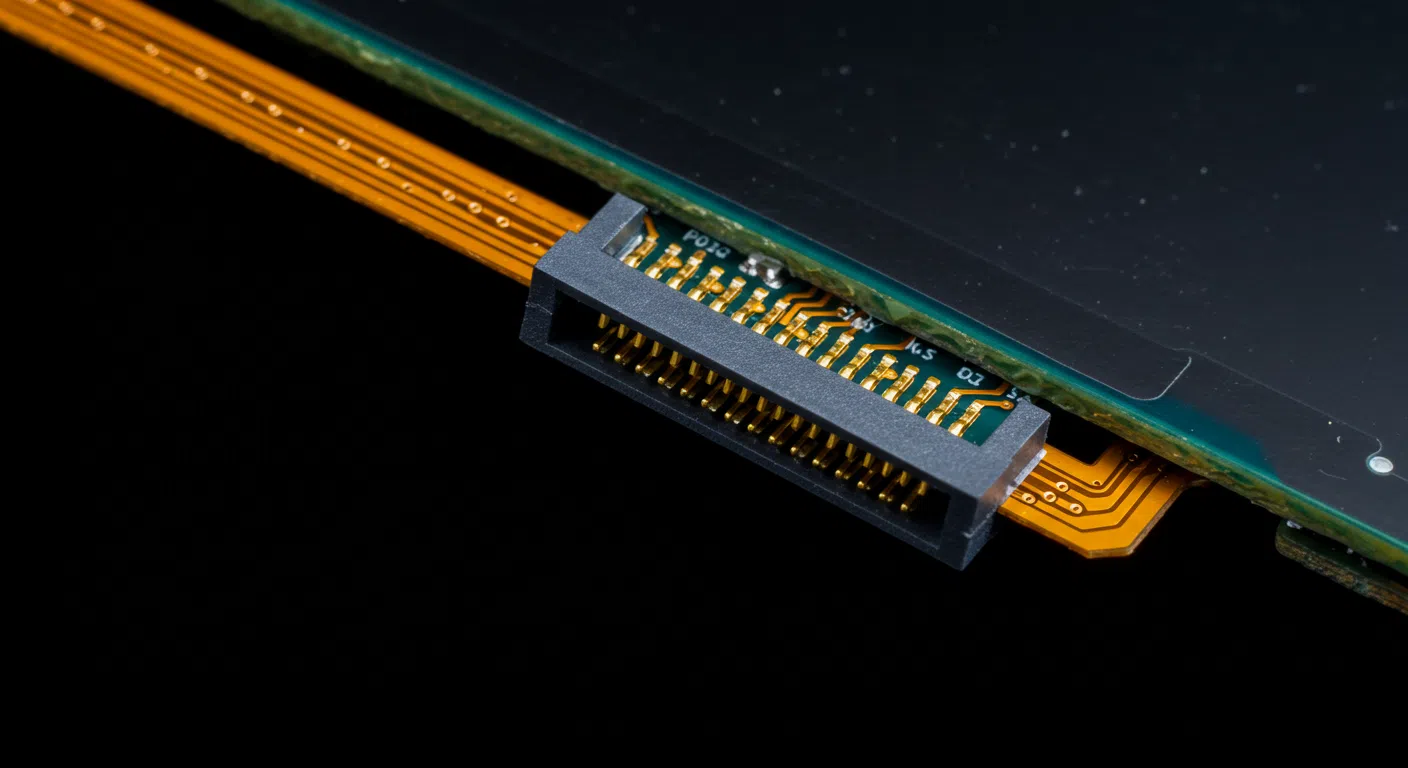
MIPI-DSI commonly uses 24-pin or 39-pin FPC connectors with 0.5mm pitch, while LVDS employs various connector types from simple pin headers to specialized high-speed connectors. SPI interfaces typically use standard 2.54mm pin headers or small FPC connectors.
| Interface | Common Connectors | Pitch | Cable Type |
|---|---|---|---|
| MCU | Pin headers, FPC | 2.54mm, 1.0mm | Parallel ribbon |
| SPI | Pin headers, FPC | 2.54mm, 1.0mm | 4-wire cable |
| RGB | Pin headers, FPC | 1.0mm, 0.8mm | Multi-conductor flat |
| LVDS | FPC, Micro-coax | 0.5mm, 1.0mm | Differential pairs |
| MIPI-DSI | 24-pin FPC, 39-pin FPC | 0.5mm | Shielded FPC |
| eDP | Micro-coax, FPC | 0.4mm, 0.5mm | High-speed differential |
MIPI connectors use fine-pitch FPC (Flexible Printed Circuit) technology. The 24-pin configuration suits 2-lane implementations while 39-pin supports 4-lane plus additional control signals(What Are the Key Differences Between FFC and FPC?).
LVDS connectors vary from simple FPC for short distances to micro-coaxial assemblies for longer cable runs. The differential nature requires controlled impedance cables, typically 100-ohm differential.
Cable length limitations affect connector choice. SPI and MCU interfaces work with simple ribbon cables up to 30cm. LVDS supports cables up to 10 meters with proper termination. MIPI-DSI typically limits cable length to under 20cm due to high-speed signaling requirements.
How do I wire each interface to a host controller or MCU?
Wiring requirements vary dramatically between interface types, from simple point-to-point connections to complex high-speed differential routing.
Wiring complexity increases with interface speed and pin count. SPI requires basic 4-wire connections, while MIPI-DSI demands careful impedance control and length matching. Proper grounding and power distribution become critical for all high-speed interfaces.
For SPI interfaces, I recommend using short, direct connections with adequate ground planes. Keep clock and data traces away from switching power supplies to minimize noise.
RGB interfaces require careful attention to signal integrity. Route all data lines with matched lengths to prevent skew. Use ground guards between traces and minimize via usage on high-speed signals.
MIPI-DSI wiring demands precision. Differential pairs must maintain 100-ohm impedance with tight coupling. Keep total trace length under 15cm and match lane lengths within 0.1mm.
Power supply bypassing becomes critical for all interfaces. Place decoupling capacitors close to display connectors, with values ranging from 0.1µF ceramic to 10µF tantalum depending on current requirements.
Conclusion
Selecting the right LCD interface requires balancing resolution needs, power consumption, EMI requirements, and implementation complexity. MCU and SPI interfaces excel for simple applications, while MIPI-DSI and eDP enable today’s high-resolution displays with optimal power efficiency.
FAQ
Which LCD interface is best for low-power, battery-operated devices?
For low-power designs, SPI and MCU interfaces are ideal. They use low clock speeds and minimal pins, keeping both power consumption and EMI low.
Can I drive a high-resolution panel over SPI?
No. SPI’s data rate tops out around 50 Mbps, making it impractical for resolutions above QVGA (320×240). For HD or higher, use MIPI-DSI or eDP instead.
Do I need special hardware to use MIPI-DSI or eDP?
Yes. You need a controller block in your SoC or a separate bridge chip. Standard GPIOs can’t handle the high speeds or differential signaling these interfaces require.
How do I reduce EMI when using a parallel RGB interface?
Keep all data and sync traces length-matched, add proper ground planes, use shielding on FFC cables, and follow the panel’s recommended termination resistors.
What’s the quickest way to verify my display wiring?
Power up and attempt to show solid red, green, then blue screens. If each color displays correctly, your power rails and basic signal connections are likely correct.