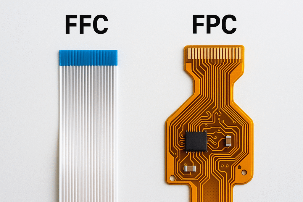
FFC (Flexible Flat Cable) is a simple flat ribbon cable with conductors sandwiched between insulating layers, while FPC (Flexible Printed Circuit) is a complete circuit board that can bend, featuring etched circuit patterns and the ability to mount components.
What Are the Construction and Materials Differences Between FFC and FPC?
Understanding the fundamental construction differences between FFC and FPC helps explain their distinct capabilities and applications.
FFCs use a simple lamination process where flat copper conductors are sandwiched between polyester (PET) or polyimide insulating films, while FPCs employ complex PCB manufacturing techniques including etching, drilling, and multi-layer lamination on flexible substrates.
The simplicity of this construction makes FFCs relatively thick compared to FPCs, typically measuring between 0.5mm to 2.54mm in thickness. The insulating films are bonded using thermal adhesives that increase the cable’s lifespan. This sandwich structure creates a product that’s cost-effective but limited in terms of circuit complexity(What EMI/EMC Rules Must Automotive LCD Displays Follow?).
FPC Manufacturing Complexity
FPCs undergo a sophisticated manufacturing process similar to traditional PCB fabrication but adapted for flexible materials. The process begins with flexible copper-clad laminate (FCCL), typically using polyimide as the base material due to its excellent thermal resistance and flexibility.
This complex process allows FPCs to achieve much thinner profiles, typically ranging from 0.15mm to 0.3mm, while supporting multiple layers and complex circuit patterns.
Material Performance Characteristics
| Characteristic | FFC | FPC |
|---|---|---|
| Base Material | PET/PEN | Polyimide (PI) |
| Temperature Resistance | Up to 125°C | Up to 280°C |
| Thickness Range | 0.5-2.54mm | 0.15-0.3mm |
| Copper Thickness | 35-125 microns | Variable, optimized per layer |
| Flexibility | Good | Excellent |
The material choices directly impact performance capabilities. Polyimide’s superior thermal stability and mechanical properties make FPCs suitable for demanding applications, while PET-based FFCs offer adequate performance for cost-sensitive applications.
How Do Technical Capabilities of FFC and FPC Compare?
The technical capabilities of FFC and FPC differ significantly, affecting their suitability for various applications and operating conditions.
FPCs support controlled impedance designs, high-frequency signal transmission, and complex multi-layer constructions, while FFCs are limited to simple point-to-point connections without impedance control capabilities.
Signal Integrity and Impedance Control
FPCs excel in high-frequency applications where signal integrity is critical. They can achieve precise impedance control through careful design of trace geometry, dielectric thickness, and layer stackups. Common impedance targets include 50Ω and 75Ω for single-ended signals, and 90Ω to 100Ω for differential pairs.
FFCs, in contrast, lack impedance control capabilities due to their simple parallel conductor arrangement. They’re suitable only for low-frequency signals below 10-20 MHz where impedance matching isn’t critical. The flat ribbon structure creates unpredictable impedance variations that make them unsuitable for high-speed digital or RF applications.
Temperature and Environmental Performance
The temperature capabilities differ substantially between the two technologies:
| Parameter | FFC | FPC |
|---|---|---|
| Operating Temperature | -55°C to +105°C | -40°C to +125°C (standard) |
| High-temp variants | Up to 125°C | Up to 280°C |
| Thermal Cycling | Limited | Excellent |
| Chemical Resistance | Moderate | Excellent |
| UV Resistance | Poor | Good |
Mechanical Durability and Flex Life
Dynamic flexing capabilities represent another significant difference. High-quality FPCs designed for dynamic applications can endure over 1 million bend cycles when properly designed.
FFCs have more limited flex life, particularly in dynamic applications. While they can handle thousands of cycles in static bend-to-install applications, they’re not suitable for continuous flexing applications like printer heads or folding displays.
Which Is More Flexible and Durable: FFC or FPC?
The mechanical properties and long-term reliability characteristics of FFC and FPC circuits determine their suitability for different operational environments.
FPCs offer superior mechanical durability with the ability to withstand millions of flex cycles and harsh environmental conditions, while FFCs provide adequate flexibility for static installations at lower cost.
Bend Radius and Flexibility Limits
The minimum bend radius is a critical specification that affects both immediate installation and long-term reliability. For FPCs, the recommended minimum bend radius is:
- Double-layer: 12 × circuit thickness (minimum)
- Multilayer: 24 × circuit thickness (minimum)
Dynamic vs. Static Applications
| Application Type | FFC Suitability | FPC Suitability |
|---|---|---|
| Static bend-to-fit | Excellent | Good |
| Occasional flexing | Good | Excellent |
| Continuous flexing | Poor | Excellent |
| Vibration resistance | Moderate | High |
| Shock resistance | Moderate | High |
FPCs excel in dynamic applications due to their robust construction and material properties. The polyimide substrate provides excellent fatigue resistance, while the etched copper patterns can be optimized for stress distribution. Applications like printer heads, folding displays, and robotic joints rely on this superior dynamic performance.
Long-term Reliability Factors
Several factors affect the long-term durability of flexible circuits:
Environmental Stress Factors:
- Temperature cycling effects on material expansion
- Humidity impact on adhesive bonds and copper oxidation
- Chemical exposure from cleaning agents or atmospheric pollutants
- UV degradation of substrate materials
Mechanical Stress Factors:
- Repeated flexing causing copper fatigue
- Creep and stress relaxation in polymer substrates
- Vibration-induced micro-movements
- Installation stress concentrations
Design Optimization for Durability
To maximize durability in both FFC and FPC designs:
For FFCs:
- Use appropriate pitch spacing for the application
- Implement proper strain relief at connection points
- Avoid sharp bends and maintain generous bend radii
- Consider environmental protection coatings for harsh conditions
For FPCs:
- Optimize trace routing for the expected flex pattern
- Use hatched ground planes instead of solid copper in flex areas
- Implement proper layer stacking and adhesive selection
- Design appropriate stiffener placement for support
What About Cost and Manufacturing Considerations?
The economic factors and manufacturing complexities significantly influence the choice between FFC and FPC solutions for any given application.
FFCs offer substantial cost advantages due to simpler manufacturing processes and materials, while FPCs command higher prices but provide enhanced functionality and performance that can justify the investment in demanding applications.
Manufacturing Process Complexity
The manufacturing process differences directly impact both cost and lead times:
FFC Manufacturing:
- Simple lamination process requiring minimal equipment
- Automated production lines with high throughput
- Limited customization options
- Standard pitch options (0.5mm to 2.54mm)
- Quick turnaround times (days to weeks)
FPC Manufacturing:
- Complex PCB fabrication requiring specialized equipment
- Multiple process steps including etching, drilling, and lamination
- Extensive customization capabilities
- Longer lead times due to process complexity (weeks to months)
- Higher setup costs for tooling and fixtures
Cost Structure Analysis
| Cost Factor | FFC | FPC |
|---|---|---|
| Material Cost | Low (PET/PEN) | High (Polyimide) |
| Processing Cost | Low | High |
| Tooling Cost | Minimal | Significant |
| Volume Economics | Excellent | Good |
| Customization Cost | Limited | Moderate |
Where Are FFC and FPC Used in Real Applications?
FFCs dominate in cost-sensitive consumer electronics and simple board-to-board connections, while FPCs are essential for high-performance applications in automotive, medical, aerospace, and mobile devices where reliability and miniaturization are paramount.
FFC Application Domains
FFCs find widespread use in applications where cost-effectiveness and simple connectivity are primary requirements:
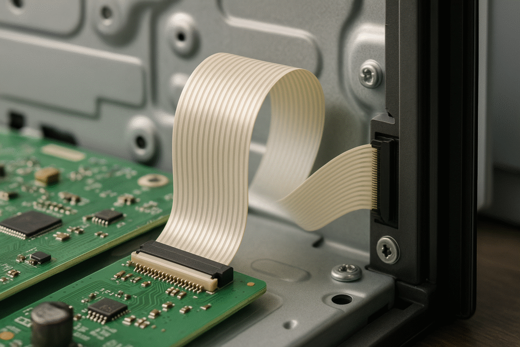
Consumer Electronics:
- LCD TVs and monitors for internal connections
- Home appliances like printers, copiers, and kerosene heaters
- Audio equipment including stereos and video recorders
- Gaming consoles for simple board interconnections
Industrial Applications:
- Control panels with limited space constraints
- Basic automation systems requiring flexible connections
- Test equipment for temporary connections
- Simple robotic applications with minimal flex requirements
FPC Application Excellence
FPCs demonstrate their superiority in demanding applications requiring advanced performance characteristics:
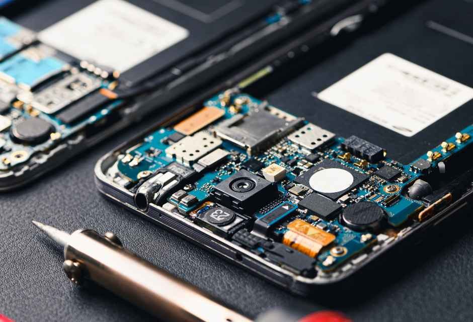
Mobile and Wearable Devices:
- Smartphones for camera modules and display connections
- Tablets for battery connections and internal routing
- Smartwatches requiring tight bend radii and reliability
- Fitness trackers with dynamic flexing requirements
Automotive Electronics:
- Engine control units operating in high-temperature environments
- Advanced driver assistance systems (ADAS) requiring signal integrity
- Infotainment systems with complex interconnections
- Electric vehicle battery management systems
Medical Applications:
- Implantable devices requiring biocompatible materials
- Portable diagnostic equipment with space constraints
- Surgical instruments with dynamic movement requirements
- Patient monitoring systems requiring reliability
Aerospace and Defense:
- Satellite systems requiring lightweight, reliable connections
- Avionics equipment with stringent reliability requirements
- Communication systems operating in harsh environments
- Military electronics requiring high durability
Application Selection Criteria
| Requirement | FFC Preferred | FPC Preferred |
|---|---|---|
| Cost sensitivity | ✓ | |
| High-speed signals | ✓ | |
| Dynamic flexing | ✓ | |
| High temperature | ✓ | |
| Space constraints | ✓ | |
| EMI shielding | ✓ | |
| Component integration | ✓ | |
| Simple connectivity | ✓ |
Industry-Specific Requirements
Automotive Industry:
The automotive sector increasingly relies on FPCs for electronic systems. Modern vehicles contain sophisticated electronics for engine management, safety systems, and infotainment. FPCs provide the reliability needed for automotive applications while withstanding temperature extremes from -40°C to +125°C and vibration conditions(What Temperature Range Can LCD Modules Safely Operate In?).
Medical Device Industry:
Medical applications demand the highest reliability standards. FPCs meet stringent regulatory requirements and provide the miniaturization needed for advanced medical devices. The ability to create complex, reliable circuits in compact form factors makes FPCs essential for modern medical technology(What Special Requirements Do Medical LCD Panels Have?).
Consumer Electronics:
The consumer electronics market drives demand for both technologies. FFCs serve cost-sensitive applications like basic appliances and peripherals, while FPCs enable the advanced functionality found in smartphones, tablets, and wearable devices(What Are the Parts of a Smart Home?).
How Do Connector Compatibility and Assembly Differ?
The connector ecosystem and assembly methods for FFC and FPC technologies present distinct advantages and challenges that significantly impact design decisions and manufacturing processes.
Both FFC and FPC systems utilize ZIF (Zero Insertion Force) and LIF (Low Insertion Force) connectors, but FPCs offer greater design flexibility with connector placement and orientation options, while FFCs provide standardized, cost-effective connection solutions(What Is a ZIF Connector and How Does It Work?).
Connector Types and Mechanisms
The connector landscape for flexible circuits has evolved to address the specific needs of both technologies:
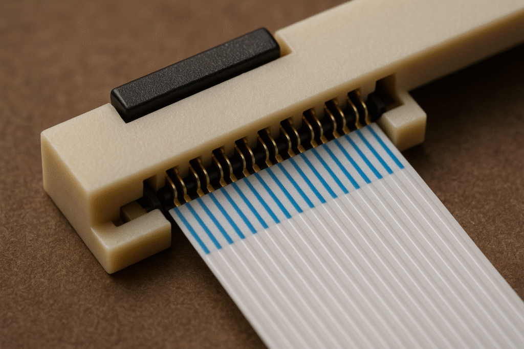
ZIF Connectors (Zero Insertion Force):
- Require virtually no force during cable insertion
- Feature locking mechanisms including slider cover, front flip, and back flip types
- Provide secure connections with minimal risk of damage during assembly
- Support pitches from 0.3mm to 2.54mm
LIF Connectors (Low Insertion Force):
- Require minimal force but more than ZIF connectors
- Often provide better retention force and durability
- Available for higher pin counts and current ratings
- Cost-effective alternative to ZIF for many applications
Connector Specifications and Performance
| Connector Type | Pitch Range | Contact Count | Operating Temperature | Current Rating |
|---|---|---|---|---|
| ZIF FFC/FPC | 0.3-2.54mm | 2-250 contacts | -40°C to +125°C | 0.5-2.0A |
| LIF FFC/FPC | 0.5-2.0mm | 2-120 contacts | -40°C to +125°C | 0.5-3.0A |
| High-temp variants | 0.5-1.0mm | 10-68 contacts | -40°C to +125°C | 0.5A |
Conclusion
The choice between FFC and FPC ultimately depends on balancing performance requirements, cost constraints, and reliability needs. FFCs excel in cost-sensitive applications requiring simple connectivity, while FPCs provide superior performance for demanding applications requiring high reliability, signal integrity, and environmental resistance.
Related Articles:
What Sets Transmissive, Reflective, and Transflective LCDs Apart?
What is a Bistable Display and How Does It Work?
What Are the Key Differences Between TN and IPS LCD Panels?
Parallel vs Serial: Understanding Communication Methods
Differences Between CCFL, WLED, DLED, ELED, Mini LED, and MicroLED Backlights?
FAQ
Can FFC and FPC be used together in one device?
Yes, FFC and FPC can be combined in a single product, depending on the circuit design and application needs.
How do I choose the correct pitch for FFC or FPC connectors?
Select the pitch based on space constraints and current requirements; smaller pitches save space but may need higher assembly precision.
What should I consider for FFC or FPC in high-vibration environments?
FPC is generally preferred for high-vibration environments due to better durability and dynamic flex performance.
Are FFC and FPC affected by humidity or moisture?
Both can be affected by moisture; always choose moisture-resistant materials and proper sealing if used in humid environments.
Can I repair a damaged FFC or FPC cable myself?
FFC cables are easier to replace, while FPC repairs often require professional tools and skills due to their complexity.