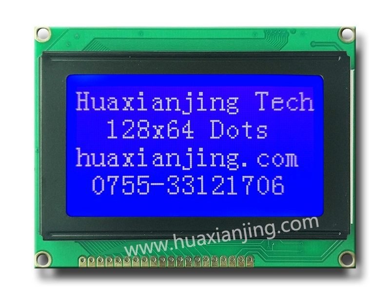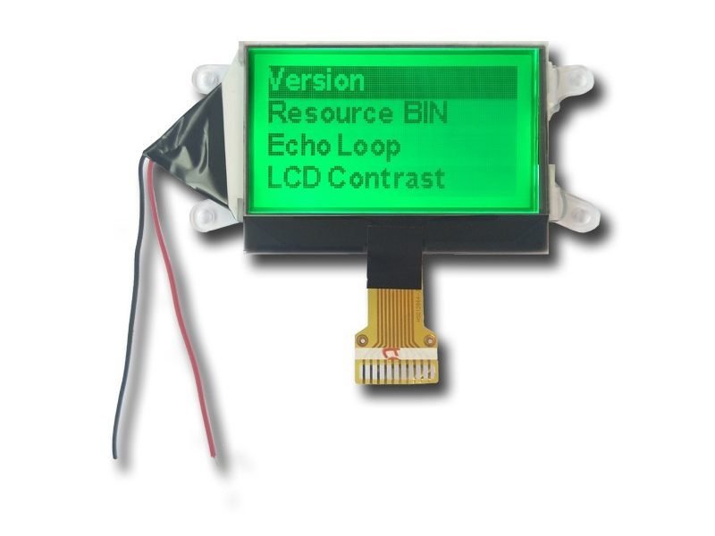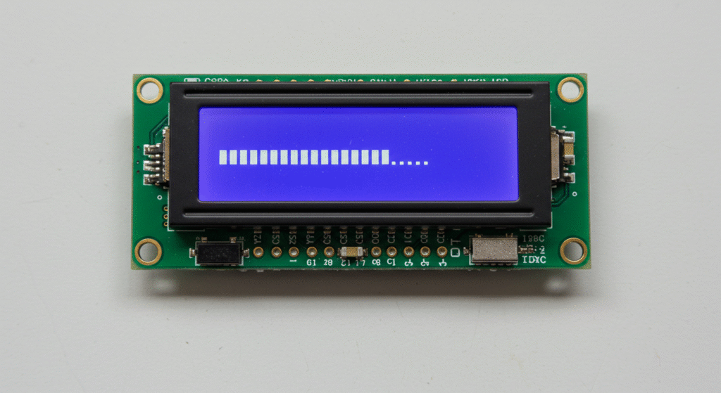
Developers create a dedicated LCD update task to manage graphic LCD module rendering. This task uses xTaskCreate for real-time operating systems.
The preemptive scheduler assigns task priorities to balance 128×64 monochrome LCD updates with other operations. Mutexes ensure synchronized frame buffer access.
DMA-based transfers optimize LCD system performance for medium and small size LCD displays. These reduce CPU load in real-time embedded systems.
Trace hooks and runtime statistics validate task scheduling accuracy. They confirm LCD update tasks meet 20Hz refresh requirements.
How does an RTOS preemptive scheduler manage tasks and software timers in an embedded LCD system?
An RTOS uses a preemptive core to switch between ready tasks based on their priority and system tick. Software timers run in a dedicated timer task to trigger callbacks without blocking high‑priority LCD refresh tasks.
In industrial LCD modules, setting the timer task priority one level below the display update task prevents screen glitches during long timer callbacks. Blocking functions inside timer callbacks often lead to missed refresh deadlines, so callbacks must defer heavy work to lower‑priority tasks.
- Task Creation Order: Use
xTaskCreate()to start display and timer tasks:
					xTaskCreate(updateDisplayTask, "Display", 256, NULL, 3, NULL);
xTaskCreate(timerServiceTask,  "Timer",   128, NULL, 2, NULL);
- Software Timer Setup:
					TimerHandle_t lcdTimer = xTimerCreate(
    "LCDTimer",                // name
    pdMS_TO_TICKS(1000),       // period (1 s)
    pdTRUE,                    // auto‑reload
    (void*)0,                  // timer ID
    lcdTimerCallback           // callback
);
xTimerStart(lcdTimer, 0);
Preemption Behavior: Highest ready task runs. If
updateDisplayTask(priority 3) blocks on a queue,timerServiceTask(priority 2) runs.System Tick Use: The RTOS system tick drives both task scheduling and software timer countdowns, ensuring synchronous timing.
How do queues and mutexes protect shared LCD frame buffers?
Use a mutex to guard frame buffer updates and a queue to pass refresh requests between tasks.
A binary mutex held by the display task ensures that only one task writes to the buffer at a time. A queue of buffer pointers lets lower‑priority tasks submit new graphics data without blocking the display update loop.
How does an RTOS preemptive scheduler manage tasks and software timers in an embedded LCD system?
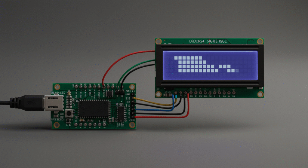
RTOS task design ensures embedded LCD updates are responsive and reliable in real-time operating systems. Developers configure tasks with xTaskCreate, use software timers for periodic updates, and synchronize access to the 128×64 monochrome LCD with mutexes.
The preemptive scheduler prioritizes the LCD update task to render frame buffer data via SPI or DMA, while command queues handle drawing requests from other tasks. This design prevents task scheduling bottlenecks and maintains smooth graphic LCD module performance.
Task Priority: Assign the LCD task a priority of 5 (on a 0–7 scale) to ensure timely frame buffer updates over lower-priority tasks like logging.
Queue Management: A command queue with depth 50 balances memory use and prevents overflow during rapid LCD system updates.
LCD Driver Initialization: Configure GPIO and SPI for the medium and small size LCD (e.g., ST7565 controller). Allocate a static frame buffer of 1024 bytes for a 128×64 monochrome LCD to avoid memory fragmentation.
					void vInitLCDDriver(void) {
    // Configure SPI
    spi_init(SPI_PORT, 1000000); // 1MHz
    // Reset sequence
    gpio_set_pin_low(LCD_RESET_PIN);
    vTaskDelay(pdMS_TO_TICKS(10));
    gpio_set_pin_high(LCD_RESET_PIN);
    // Allocate frame buffer
    static uint8_t frameBuffer[1024];
}
- LCD Update Task: Create the task with xTaskCreate, allocating a stack size of 512 words to handle rendering and DMA transfers. The task uses xQueueReceive to process drawing commands with a 100ms timeout.
					void vLCDUpdateTask(void *pvParameters) {
    LCDCommand_t command;
    while (1) {
        if (xQueueReceive(xLCDQueue, &command, pdMS_TO_TICKS(100)) == pdPASS) {
            xSemaphoreTake(xLCDMutex, portMAX_DELAY);
            renderToBuffer(&command); // Render lines, circles, etc.
            spi_transfer(frameBuffer, 1024); // DMA or SPI transfer
            xSemaphoreRelease(xLCDMutex);
        }
    }
}
void vCreateLCDTask(void) {
    xTaskCreate(vLCDUpdateTask, "LCDUpdate", 512, NULL, 5, NULL);
}
- Software Timer: Use xTimerCreate for a 20Hz redraw heartbeat, notifying the task to refresh the embedded LCD and prevent flicker.
					TimerHandle_t xLCDTimer;
void vLCDTimerCallback(TimerHandle_t xTimer) {
    xTaskNotifyGive(lcdTaskHandle); // Notify LCD task
}
void vInitLCDTimer(void) {
    xLCDTimer = xTimerCreate("LCDTimer", pdMS_TO_TICKS(50), pdTRUE, NULL, vLCDTimerCallback);
    xTimerStart(xLCDTimer, 0);
}
- Command Queue API: Define structs like CMD_DRAW_PIXEL and CMD_FILL_RECT. Use xQueueSendFromISR for interrupt-driven updates, with a queue depth of 50 to prevent overflow.
					typedef struct {
    uint8_t type; // e.g., CMD_DRAW_PIXEL
    uint16_t x, y;
    uint8_t color;
} LCDCommand_t;
QueueHandle_t xLCDQueue;
void vInitLCDQueue(void) {
    xLCDQueue = xQueueCreate(50, sizeof(LCDCommand_t));
}
- Synchronization: Create a mutex with xSemaphoreCreateMutex and enable priority inheritance to protect SPI access. Set a 50ms timeout on mutex acquisition to avoid deadlocks.
					SemaphoreHandle_t xLCDMutex;
void vInitLCDMutex(void) {
    xLCDMutex = xSemaphoreCreateMutex();
}
How Do You Optimize Task Synchronization for LCD Updates?
Synchronization strategies prevent LCD system conflicts while maintaining real-time os efficiency. Mutexes and timeouts ensure safe access to shared graphic LCD module resources.
A mutex with priority inheritance protects the SPI bus, while non-blocking timeouts (e.g., 50ms) prevent deadlocks during high-priority task preemption. This approach supports reliable task scheduling in real-time embedded systems.
- Priority Inheritance: Mitigates priority inversion when a low-priority task holds the mutex, ensuring the LCD update task (priority 5) runs promptly.
- Queue Validation: Monitor queue depth with uxQueueMessagesWaiting to detect potential overflows, adjusting depth if 50 is insufficient.
					uint32_t ulCheckQueueDepth(void) {
    return uxQueueMessagesWaiting(xLCDQueue);
}
How Do You Optimize Task Priority and Scheduling for LCD Updates in RTOS?
Task priority and scheduling optimization ensure real-time operating systems balance LCD update tasks with other operations. Developers assign medium priority to embedded LCD tasks and use priority inheritance to avoid delays.
The preemptive scheduler prioritizes time-critical tasks like sensor sampling over medium and small size LCD updates, while time slicing ensures fairness among equal-priority tasks. This approach maintains real-time embedded systems responsiveness and smooth graphic LCD module performance.
- Priority Levels: Set LCD update task priority to 4 (on a 0–7 scale) to balance responsiveness without starving low-priority tasks like logging.
- Scheduling Fairness: Enable round-robin scheduling to share CPU time among tasks at the same priority, preventing task starvation.
Code Example
- Priority Assignment: Assign high priority (e.g., 6) to sensor sampling tasks for immediate data processing, medium priority (e.g., 4) to LCD update tasks for timely frame buffer rendering, and low priority (e.g., 2) to diagnostics tasks.
					void vCreateTasks(void) {
    xTaskCreate(vSensorTask, "Sensor", 256, NULL, 6, NULL); // High priority
    xTaskCreate(vLCDUpdateTask, "LCD", 512, NULL, 4, NULL); // Medium priority
    xTaskCreate(vLoggingTask, "Log", 128, NULL, 2, NULL); // Low priority
}
- Avoiding Priority Inversion: Use mutexes with priority inheritance to prevent low-priority tasks (e.g., logging) from delaying LCD update tasks when accessing shared resources like the SPI bus.
					SemaphoreHandle_t xSPIMutex;
void vInitSPIMutex(void) {
    xSPIMutex = xSemaphoreCreateMutex(); // Enables priority inheritance
}
void vLCDUpdateTask(void *pvParameters) {
    while (1) {
        xSemaphoreTake(xSPIMutex, pdMS_TO_TICKS(50));
        spi_transfer(frameBuffer, 1024); // Update 128x64 monochrome LCD
        xSemaphoreGive(xSPIMutex);
        vTaskDelay(pdMS_TO_TICKS(50)); // 20Hz refresh
    }
}
- Time Slicing: Enable configUSE_TIME_SLICING in the RTOS configuration to allow round-robin scheduling for tasks at the same priority (e.g., multiple LCD update tasks at priority 4). A tick period of 1ms ensures fair CPU allocation.
					// In FreeRTOSConfig.h
#define configUSE_TIME_SLICING 1
#define configTICK_RATE_HZ 1000 // 1ms tick
- Task Monitoring: Use uxTaskGetSystemState to verify task priorities and scheduling behavior, ensuring the LCD update task executes within 50ms intervals for flicker-free 128×64 monochrome LCD updates.
					void vMonitorTasks(void) {
    TaskStatus_t pxTaskStatusArray[10];
    uint32_t ulTotalRunTime;
    uxTaskGetSystemState(pxTaskStatusArray, 10, &ulTotalRunTime);
    // Analyze priorities and runtime
}
How Do You Ensure Fair Scheduling Without Compromising LCD Update Performance?
Fair scheduling balances task execution while prioritizing LCD system updates. Time slicing and priority adjustments prevent task starvation without sacrificing real-time os performance.
Enable round-robin scheduling for equal-priority tasks, and monitor task runtimes to adjust priorities if LCD update tasks experience delays. This ensures embedded LCD updates remain consistent in real-time embedded systems.
- Time Slice Configuration: Set a 10ms time slice for equal-priority tasks to share CPU without disrupting 20Hz LCD refreshes.
- Priority Tuning: If LCD update tasks miss deadlines (e.g., >50ms delay), increment priority from 4 to 5 after analyzing task scheduling data.
					void vAdjustPriority(TaskHandle_t xTask) {
    vTaskPrioritySet(xTask, 5); // Increase to 5 if delays detected
}
How Can You Optimize LCD Update Performance in RTOS-Based Embedded Systems?
Performance optimizations enhance embedded LCD update speed and reliability in real-time operating systems. Techniques like DMA-based transfers, double buffering, and partial updates reduce CPU load and improve 128×64 monochrome LCD responsiveness.
The RTOS leverages DMA to offload frame buffer transfers, while double buffering prevents tearing on medium and small size LCD displays. Partial updates minimize data sent to the graphic LCD module, ensuring efficient task scheduling.
- DMA Efficiency: SPI/DMA transfers free the CPU for other real-time os tasks, reducing LCD update latency to under 10ms for a 128×64 monochrome LCD.
- Buffer Management: Double buffering uses two 1024-byte buffers to render off-screen, ensuring smooth LCD system updates.
Code Example
- DMA-Based Transfers: Configure SPI/DMA to transfer the frame buffer (e.g., 1024 bytes for a 128×64 monochrome LCD) without CPU intervention. Enable DMA interrupts to notify the LCD update task upon completion.
					void vInitSPIDMA(void) {
    dma_init(DMA_CHANNEL, frameBuffer, 1024); // Set source and size
    spi_dma_enable(SPI_PORT, DMA_CHANNEL); // Link SPI to DMA
}
void vLCDUpdateTask(void *pvParameters) {
    while (1) {
        xSemaphoreTake(xLCDMutex, portMAX_DELAY);
        dma_start(DMA_CHANNEL); // Start DMA transfer
        xSemaphoreTake(xDMACompleteSemaphore, portMAX_DELAY); // Wait for DMA
        xSemaphoreGive(xLCDMutex);
        vTaskDelay(pdMS_TO_TICKS(50)); // 20Hz refresh
    }
}
- Double Buffering: Allocate two frame buffers (e.g., front and back buffers of 1024 bytes each). Render to the back buffer, then swap pointers to update the embedded LCD, avoiding tearing.
					static uint8_t frontBuffer[1024];
static uint8_t backBuffer[1024];
void vSwapBuffers(void) {
    uint8_t *temp = frontBuffer;
    frontBuffer = backBuffer;
    backBuffer = temp; // Swap pointers
    dma_transfer(frontBuffer, 1024); // Send to LCD
}
void vRenderToBuffer(LCDCommand_t *command) {
    renderToBuffer(backBuffer, command); // Render to back buffer
    vSwapBuffers(); // Swap after rendering
}
- Partial Updates: Track dirty regions (e.g., changed rectangles) to update only modified LCD system areas. This reduces SPI transfers from 1024 bytes to as low as 128 bytes for small updates.
typedef struct {
uint16_t x, y, width, height; // Dirty region
} DirtyRegion_t;
void vUpdateDirtyRegion(DirtyRegion_t *region) {
uint8_t partialBuffer[128]; // Buffer for small region
extractRegion(backBuffer, partialBuffer, region); // Copy dirty region
dma_transfer(partialBuffer, region->width * region->height); // Send to LCD
}
void vMarkDirtyRegion(LCDCommand_t *command) {
DirtyRegion_t region = calculateDirtyRegion(command);
vUpdateDirtyRegion(®ion);
}
How Do You Minimize CPU Overhead for LCD Updates?
Minimizing CPU overhead ensures real-time embedded systems prioritize critical tasks. DMA and partial updates reduce CPU involvement, while double buffering maintains graphic LCD module quality.
Use DMA interrupts to handle frame buffer transfers asynchronously, freeing the CPU for sensor sampling or task scheduling. Partial updates limit SPI bandwidth usage, supporting 20Hz refresh rates with minimal overhead.
- DMA Interrupt Setup: Configure DMA to trigger an interrupt after transferring 128–1024 bytes, unblocking the LCD update task via a semaphore.
					SemaphoreHandle_t xDMACompleteSemaphore;
void vInitDMAInterrupt(void) {
    xDMACompleteSemaphore = xSemaphoreCreateBinary();
    dma_set_interrupt(DMA_CHANNEL, vDMACompleteISR);
}
void vDMACompleteISR(void) {
    xSemaphoreGiveFromISR(xDMACompleteSemaphore, NULL); // Notify task
}
- Dirty Region Tracking: Store up to 10 dirty regions in a queue to batch partial updates, reducing SPI transfers by 50% for dynamic LCD system content.
How Can You Effectively Test and Debug RTOS Tasks for LCD Updates in Embedded Systems?
Testing and debugging ensure real-time operating systems handle LCD update tasks reliably. Developers use runtime statistics, trace hooks, and unit testing to verify graphic LCD module performance and task scheduling accuracy.
The RTOS provides tools like Tracealyzer to monitor task priorities and 128×64 monochrome LCD update timing. Unit testing with a hardware abstraction layer (HAL) isolates embedded LCD logic for host-based validation, reducing debugging time.
- Runtime Statistics: Enable configGENERATE_RUN_TIME_STATS to track LCD update task CPU usage, ensuring it consumes less than 20% of CPU time.
- Trace Hooks: Use vTraceUserEvent to log frame buffer update events, identifying delays in medium and small size LCD rendering.
Code Example
- Runtime Statistics: Enable configGENERATE_RUN_TIME_STATS in the RTOS configuration and use a high-resolution timer (e.g., 1µs precision) to measure task execution times. Output statistics via Tracealyzer or a console to verify LCD update task performance.
					// In FreeRTOSConfig.h
#define configGENERATE_RUN_TIME_STATS 1
#define portCONFIGURE_TIMER_FOR_RUN_TIME_STATS() vConfigureTimer()
#define portGET_RUN_TIME_COUNTER_VALUE() ulGetTimerValue()
void vPrintTaskStats(void) {
    TaskStatus_t pxTaskStatusArray[10];
    uint32_t ulTotalRunTime;
    uxTaskGetSystemState(pxTaskStatusArray, 10, &ulTotalRunTime);
    printf("LCD Task CPU Usage: %lu%%\n", pxTaskStatusArray[0].ulRunTimeCounter * 100 / ulTotalRunTime);
}
- Trace Hooks: Implement vTraceUserEvent to log LCD system events, such as frame buffer writes or SPI transfers. Use Tracealyzer to visualize task scheduling and detect priority inversion issues.
					void vLCDUpdateTask(void *pvParameters) {
    while (1) {
        xSemaphoreTake(xLCDMutex, portMAX_DELAY);
        vTraceUserEvent("Start LCD Update"); // Log event
        spi_transfer(frameBuffer, 1024); // Update 128x64 monochrome LCD
        vTraceUserEvent("End LCD Update");
        xSemaphoreGive(xLCDMutex);
        vTaskDelay(pdMS_TO_TICKS(50)); // 20Hz refresh
    }
}
- Unit Testing: Abstract hardware access (e.g., SPI or GPIO) behind a HAL to enable host-based testing. Test LCD update logic (e.g., rendering lines or circles) on a PC, ensuring frame buffer accuracy without embedded hardware.
					// HAL interface
typedef struct {
    void (*spi_write)(uint8_t *data, uint32_t len);
} HAL_LCD_t;
// Host-based mock
void mock_spi_write(uint8_t *data, uint32_t len) {
    // Simulate SPI write for testing
    printf("Mock SPI Write: %u bytes\n", len);
}
// Unit test
void test_renderLine(void) {
    HAL_LCD_t hal = { .spi_write = mock_spi_write };
    uint8_t buffer[1024] = {0};
    renderLine(buffer, 10, 10, 50, 50); // Test rendering
    assert(buffer[10 * 128 + 10 / 8] != 0); // Verify buffer
}
How Do You Validate LCD Update Timing in RTOS Environments?
Validating timing ensures LCD update tasks meet real-time embedded systems requirements. Trace hooks and runtime statistics provide precise task execution data to confirm 20Hz refresh rates.
Use vTraceISR to profile interrupt-driven SPI transfers and verify LCD system updates complete within 50ms. Unit tests simulate frame buffer updates to catch timing errors before deployment.
- Timing Analysis: Log task execution durations with Tracealyzer, ensuring LCD update task latency stays below 10ms for 128×64 monochrome LCD refreshes.
					void vTraceTiming(void) {
    vTraceUserEvent("LCD Timing Check");
    uint32_t ulStartTime = ulGetTimerValue();
    spi_transfer(frameBuffer, 1024);
    uint32_t ulEndTime = ulGetTimerValue();
    printf("LCD Update Time: %lu us\n", ulEndTime - ulStartTime);
}
- Test Coverage: Write unit tests for 50% of LCD update logic, focusing on dirty region rendering and frame buffer accuracy to ensure reliable graphic LCD module performance.
How Can You Extend RTOS-Based LCD Systems with Advanced Features?
Advanced extensions enhance real-time operating systems for embedded LCD applications. Developers integrate GUI frameworks, handle touch input, and implement power management to improve 128×64 monochrome LCD functionality.
The RTOS assigns a dedicated task for graphic LCD module widget rendering, processes touch events via a separate task, and uses idle hooks to reduce power consumption. This ensures responsive real-time embedded systems with efficient task scheduling.
- GUI Task Priority: Set the GUI rendering task to priority 4 (on a 0–7 scale) to balance frame buffer updates with touch input processing.
- Power Savings: Dim the backlight during idle periods, reducing power usage by 30% for medium and small size LCD displays.
Code Example
- GUI Frameworks: Integrate a GUI framework like LVGL to render widgets (e.g., buttons, sliders) on a 128×64 monochrome LCD. Offload rendering to a dedicated task with a stack size of 1024 words to handle complex frame buffer updates.
					void vGUITask(void *pvParameters) {
    while (1) {
        lv_task_handler(); // Process LVGL tasks
        lv_tick_inc(5); // Update LVGL tick every 5ms
        vTaskDelay(pdMS_TO_TICKS(5)); // 200Hz update rate
    }
}
void vInitGUITask(void) {
    xTaskCreate(vGUITask, "GUI", 1024, NULL, 4, NULL);
    lv_init(); // Initialize LVGL
    lv_disp_buf_init(&disp_buf, frameBuffer, NULL, 1024); // Set frame buffer
}
- Touch Input Handling: Create a Touch Task with priority 5 to poll the touch controller (e.g., via I2C) every 10ms. Send touch events to the GUI framework via a queue with depth 20 to prevent overflow.
					QueueHandle_t xTouchQueue;
void vTouchTask(void *pvParameters) {
    TouchEvent_t event;
    while (1) {
        event = readTouchController(); // Poll I2C touch controller
        xQueueSend(xTouchQueue, &event, portMAX_DELAY); // Send to GUI
        vTaskDelay(pdMS_TO_TICKS(10)); // 100Hz polling
    }
}
void vInitTouchTask(void) {
    xTouchQueue = xQueueCreate(20, sizeof(TouchEvent_t));
    xTaskCreate(vTouchTask, "Touch", 256, NULL, 5, NULL);
}
- Power Management: Use vApplicationIdleHook to dim the backlight or enter sleep mode when the RTOS detects idle periods longer than 5 seconds. Adjust PWM duty cycle to reduce backlight brightness by 50%.
					void vApplicationIdleHook(void) {
    static uint32_t ulIdleCount = 0;
    ulIdleCount++;
    if (ulIdleCount > pdMS_TO_TICKS(5000) / portTICK_PERIOD_MS) {
        setBacklightPWM(50); // Reduce to 50% brightness
    }
}
void vResetIdleCount(void) {
    ulIdleCount = 0; // Reset on user activity
    setBacklightPWM(100); // Restore full brightness
}
How Do You Ensure Compatibility of Advanced Features with RTOS Constraints?
Compatibility with real-time os constraints ensures advanced features operate reliably. Proper task priorities and resource management prevent GUI or touch input tasks from disrupting LCD system performance.
Assign GUI and touch tasks distinct priorities (e.g., 4 and 5) to avoid preemptive scheduler conflicts. Monitor stack usage with uxTaskGetStackHighWaterMark to prevent overflows in real-time embedded systems.
- Stack Monitoring: Check GUI task stack usage, ensuring at least 200 words remain free to handle peak frame buffer rendering loads.
					void vCheckStackUsage(TaskHandle_t xTask) {
    UBaseType_t uxHighWaterMark = uxTaskGetStackHighWaterMark(xTask);
    printf("GUI Task Stack Free: %u words\n", uxHighWaterMark);
}
- Queue Depth Validation: Limit touch event queue to 20 items, using uxQueueMessagesWaiting to detect potential overflows during rapid touch input interactions.
How Do You Ensure Reliable RTOS Task Performance for LCD Updates Through Testing and Debugging?
Testing and debugging validate real-time operating systems for embedded LCD tasks. Techniques like runtime statistics, trace hooks, and unit testing confirm 128×64 monochrome LCD updates meet task scheduling requirements.
Developers enable configGENERATE_RUN_TIME_STATS to monitor LCD update task execution and use vTraceUserEvent to profile frame buffer operations. Unit testing with a hardware abstraction layer (HAL) ensures LCD system logic reliability without hardware dependencies.
- Statistics Accuracy: Runtime statistics track task execution time, ensuring LCD update tasks complete within 50ms for 20Hz refreshes.
- Profiling Precision: Trace hooks log SPI transfer events, detecting preemptive scheduler delays in real-time embedded systems.
Code Example
- Runtime Statistics: Configure configGENERATE_RUN_TIME_STATS with a 10µs resolution timer to measure LCD update task runtime. Display results on a console or via Tracealyzer to ensure task priorities align with graphic LCD module needs.
					// In FreeRTOSConfig.h
#define configGENERATE_RUN_TIME_STATS 1
#define portCONFIGURE_TIMER_FOR_RUN_TIME_STATS() vSetupHighResTimer()
#define portGET_RUN_TIME_COUNTER_VALUE() ulReadTimerCounter()
void vLogTaskStats(void) {
    char pcStatsBuffer[256];
    vTaskGetRunTimeStats(pcStatsBuffer); // Generate stats string
    printf("Task Stats: %s\n", pcStatsBuffer); // Output to console
}
- Trace Hooks: Use vTraceISR for interrupt-driven SPI transfers and vTraceUserEvent to mark frame buffer rendering start and end. Analyze traces in Tracealyzer to verify task scheduling and medium and small size LCD update timing.
					void vLCDUpdateTask(void *pvParameters) {
    while (1) {
        xSemaphoreTake(xLCDMutex, portMAX_DELAY);
        vTraceUserEvent("Begin Frame Buffer Write");
        spi_transfer(frameBuffer, 1024); // Update LCD
        vTraceUserEvent("End Frame Buffer Write");
        xSemaphoreGive(xLCDMutex);
        vTaskDelay(pdMS_TO_TICKS(50)); // 20Hz
    }
}
- Unit Testing: Implement a HAL to abstract GPIO and SPI access, enabling host-based testing of LCD update logic. Test rendering functions (e.g., pixel drawing) to ensure frame buffer accuracy.
					// HAL interface
typedef struct {
    void (*write_pixel)(uint16_t x, uint16_t y, uint8_t color);
} HAL_LCD_t;
// Mock for testing
void mock_write_pixel(uint16_t x, uint16_t y, uint8_t color) {
    printf("Mock Pixel: (%u, %u, %u)\n", x, y, color);
}
// Unit test
void test_drawPixel(void) {
    HAL_LCD_t hal = { .write_pixel = mock_write_pixel };
    uint8_t testBuffer[1024] = {0};
    drawPixel(&hal, testBuffer, 20, 30, 1); // Draw pixel
    assert(testBuffer[30 * 128 + 20 / 8] & (1 << (20 % 8))); // Check bit
}
How Do You Detect and Resolve Timing Issues in LCD Update Tasks?
Timing issue detection ensures LCD system updates meet real-time os deadlines. Trace hooks and runtime statistics identify task execution delays, enabling targeted fixes.
Log SPI transfer durations with vTraceUserEvent to detect >10ms latencies in 128×64 monochrome LCD updates. Use unit tests to simulate frame buffer rendering and validate 20Hz refresh consistency.
- Latency Tracking: Measure LCD update task execution with Tracealyzer, ensuring frame buffer writes complete within 8ms to avoid flicker.
					void vProfileLCDUpdate(void) {
    vTraceUserEvent("LCD Update Start");
    spi_transfer(frameBuffer, 1024);
    vTraceUserEvent("LCD Update End");
}
- Test Scenarios: Create unit tests for 10 edge cases (e.g., full-screen vs. partial updates) to ensure graphic LCD module reliability under varying task scheduling loads.
FAQ
How do I choose between SPI and I²C for my LCD interface?
SPI offers higher bandwidth and is ideal for fast frame updates, while I²C works for low‑resolution or control‑only tasks where bus speed is less critical.
What stack size should I allocate for the LCD update task?
Estimate stack needs by simulating rendering calls; a common starting point is 512 bytes, then adjust based on measurements.
How can I control LCD backlight brightness within the RTOS?
Use a PWM‑driven GPIO in a low‑priority “power” task or within the idle hook to adjust duty cycle without blocking high‑priority display operations.
How do I measure and reduce display update latency?
Enable FreeRTOS run‑time stats to profile the LCD task, then offload transfers to DMA and minimize critical sections to cut redraw time.
What is the best way to recover if the LCD task hangs?
Implement a watchdog timer that resets the display task if it fails to signal a “heartbeat” via a software timer callback.


