I2C lets a microcontroller talk to an LCD using only two wires: SDA (data) and SCL (clock). This setup is much simpler than older parallel interfaces that needed many more connections.
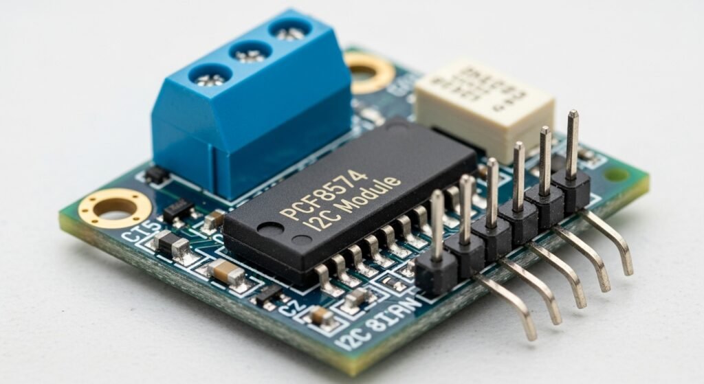
The microcontroller sends data through the I2C data bus, using an I2C protocol. An I2C module, like one based on the PCF8574 chip, turns this serial data into parallel LCD signals.
I2C supports multiple devices on the same bus. Each device has a unique address, so only the one being spoken to will respond. This helps when you’re working with more than one LCD or adding sensors to the same microcontroller.
How to Set Up I2C for LCD Communication?
To set up I2C for LCD communication, first connect the SDA (Serial Data) and SCL (Serial Clock) lines between the microcontroller and the I2C module. Then, wire the power (VCC) and ground (GND) from the LCD to the microcontroller. Finally, add pull-up resistors (typically 4.7kΩ) to both SDA and SCL to keep the bus stable. This allows reliable two-wire communication using the I2C protocol to control LCD modules(How Can a Serial In and Parallel Out Shift Register Simplify MCU to LCD Communication?).
Setting up the I2C interface requires more than just wiring. You need to ensure the module’s address matches your software configuration, often using a PCF8574-based I2C module that converts signals from the microcontroller into LCD-compatible formats. Different LCD types require slightly different configurations, depending on their internal controllers and resolution support. Actual use in embedded projects, like bicycle displays or control panels, shows that stable I2C connections greatly reduce display flicker and signal errors, especially when correct pull-ups are applied and wiring is compact.
| Component | Connection |
|---|---|
| SDA | Microcontroller I2C SDA |
| SCL | Microcontroller I2C SCL |
| VCC | 3.3V or 5V from microcontroller |
| GND | Common ground with microcontroller |
| Pull-up Resistors | 4.7kΩ between SDA/SCL and VCC |
What Are the Correct Hardware Connections for I2C and LCD?
To establish proper I2C and LCD communication, connect the SDA and SCL pins from the LCD module to the corresponding I2C port on the microcontroller. Also, provide power (VCC) and ground (GND) to the module.
In actual deployment, projects often fail due to loose connections or missing pull-up resistors. Adding external pull-ups to the SDA and SCL lines is critical to prevent floating states, which cause data corruption. When working in environments with long wires or EMI, use twisted pair cables to improve signal quality.
How Does the I2C Module Enable LCD Compatibility?
The I2C module works as a bridge between the I2C communication protocol and the parallel interface used by many LCDs. Modules like the PCF8574 receive I2C signals and convert them into 4-bit or 8-bit data compatible with standard LCD drivers(What is the difference between using an LCD in 4-bit mode versus 8-bit mode when interfacing?).
This conversion means fewer microcontroller pins are needed, making the setup efficient in compact designs. Each module comes with a configurable address, usually 7-bit, allowing multiple devices to share the same I2C bus. Engineers often use dip switches or solder pads to change the module address when working with I2C multiplexing.
| I2C Feature | Description |
|---|---|
| Protocol | Master-slave, synchronous |
| Addressing | 7-bit (default), 10-bit (optional) |
| Module Type | PCF8574, PCF8574A (with address ranges) |
| Output Conversion | Parallel to LCD pins (RS, E, D4-D7) |
Which LCD Types Work with I2C Communication?
Monochrome, TFT, and embedded LCDs all support I2C with different levels of compatibility. Monochrome LCDs with HD44780 controllers work best with PCF8574-based modules. TFT LCDs usually require dedicated graphic controllers but can still use I2C for control signals. Embedded LCDs in industrial applications often include built-in I2C support.
In practice, monochrome LCDs connected over I2C are preferred for simple UI outputs. TFTs are selected when color or resolution matters, and often need an I2C-to-SPI bridge due to bandwidth constraints. Embedded LCDs simplify design since their firmware directly supports I2C commands.
| LCD Type | I2C Support | Use Case |
|---|---|---|
| Monochrome LCD | Direct via module | Text displays, status indicators |
| TFT LCD | Partial (via MCU) | Graphic interfaces, GUIs |
| Embedded LCD | Native I2C | Industrial control, smart devices |
How Does I2C Communication Work with LCDs?
The I2C protocol enables a microcontroller to communicate with an LCD module using a two-wire interface. The microcontroller, acting as the master, sends the I2C address to the I2C module (slave), which responds with an I2C acknowledge signal. Data, such as text or cursor position, travels via the SDA line, synchronized by the SCL line. The I2C module converts this data into parallel signals for the LCD display. Timing, including start/stop conditions, ensures reliable communication at speeds like 100 kbps or 400 kbps(How do timing controllers (TCON) synchronize image data in LCDs?).
The process has three key aspects. First, the master-slave communication defines how the microcontroller initiates contact. Second, the data transfer process handles sending commands to the LCD. Third, timing and synchronization ensure data arrives correctly. In a project displaying sensor readings, a misconfigured I2C speed caused data corruption.
What Is Master-Slave Communication in I2C?
Master-slave communication in I2C means the microcontroller (master) controls when and how data is transferred. It begins the process by sending a 7-bit or 10-bit address along with a read/write bit. The LCD’s I2C module (slave) checks the address and responds with an ACK (acknowledge) if it matches.
This method avoids signal conflict, especially on shared buses. For example, when multiple I2C devices exist, the master selects only one device by address, and others stay idle. This ensures the I2C bus handles multiple LCDs or sensors without data clashes. In high-density layouts like control panels, this prevents bus congestion.
| Role | Function |
|---|---|
| Master | Sends address, data, and clock signals |
| Slave | Responds with ACK, executes commands |
| I2C Address | Uniquely identifies the slave |
| ACK Bit | Confirms reception |
					#include <Wire.h>
#define I2C_ADDR 0x27
void setup() {
  Serial.begin(9600);
  Wire.begin();
  Wire.beginTransmission(I2C_ADDR);
  if (Wire.endTransmission() == 0) {
    Serial.println("Acknowledge received from I2C module");
  } else {
    Serial.println("No acknowledge signal");
  }
}
void loop() {}
How Is Data Transferred Over I2C to LCDs?
Data transfer from the master to the LCD follows a structured pattern. The master sends bytes over SDA, which are synchronized with SCL clock pulses. Each byte might be a command (e.g., clear screen) or character data (e.g., display text). The I2C module converts this serial stream into parallel signals compatible with the LCD’s interface(How Can a Serial In and Parallel Out Shift Register Simplify MCU to LCD Communication?).
When displaying “Temp: 25C”, for instance, each letter is sent as a byte via I2C. The module stores and shifts each one to the LCD’s data bus. This process is reliable if the device receives all bytes correctly and each transfer is acknowledged. In most projects, this saves GPIO pins and simplifies wiring(How Can You Create Custom Characters on an Character LCD?).
| Transfer Stage | I2C Signal | LCD Action |
|---|---|---|
| Start Condition | SDA low, SCL high | Begin communication |
| Address + R/W | Sent on SDA | LCD module identifies itself |
| Data Byte | Sent with each clock | Interpreted by module |
| ACK/NAK | From slave | Confirm/Reject data |
| Stop Condition | SDA goes high | End communication |
					#include <Wire.h>
#define I2C_ADDR 0x27 // I2C module address
void setup() {
  Wire.begin(); // Start I2C communication
  Wire.beginTransmission(I2C_ADDR);
  Wire.write(0x80); // Set cursor position
  Wire.write(0x48); // Display 'H'
  Wire.write(0x65); // Display 'e'
  Wire.write(0x6C); // Display 'l'
  Wire.write(0x6C); // Display 'l'
  Wire.write(0x6F); // Display 'o'
  Wire.endTransmission();
}
void loop() {}
How Do Timing and Speed Affect I2C LCD Communication?
I2C timing ensures each bit is stable and valid when transmitted. The start condition occurs when SDA drops while SCL is high. Each data bit must hold stable during the SCL high period. The stop condition happens when SDA rises while SCL is high. These transitions define I2C’s structure.
The bus supports three speed modes:
- Standard Mode: 100 kbps
- Fast Mode: 400 kbps
- High-Speed Mode: 3.4 Mbps (not common for LCDs)
Real-world LCD projects usually stick to standard or fast mode for reliability. Timing diagrams are essential during debugging, especially when communication fails. Oscilloscope captures show if setup and hold times meet spec. Poor timing can lead to incorrect display behavior, especially on longer wires.
| Speed Mode | Max Frequency | Typical Use Case |
|---|---|---|
| Standard Mode | 100 kHz | Most LCD projects |
| Fast Mode | 400 kHz | Faster screen updates |
| High-Speed Mode | 3.4 MHz | Rare, high-speed sensors |
Simplifying Development with Libraries

Microcontroller libraries are pre-written code collections that handle low-level operations, allowing developers to focus on project goals rather than technical details. For I2C communication with LCDs, libraries like Wire (standard in Arduino) abstract the intricacies of the I2C protocol—such as timing and signal management—into simple, reusable functions. Similar libraries exist for other platforms, like smbus for Raspberry Pi or machine.I2C for MicroPython, offering comparable ease of use.
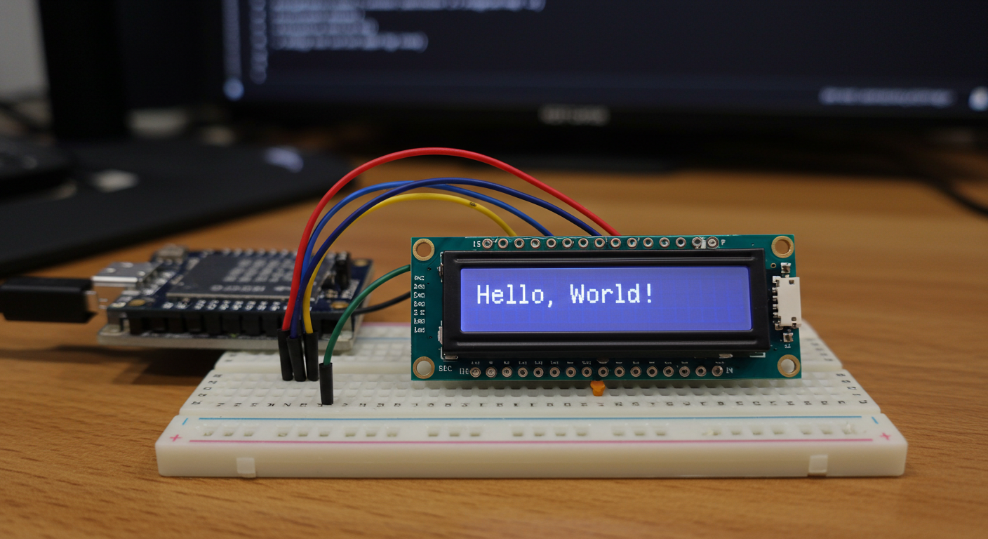
Using these libraries, you can quickly connect to an LCD and display text with minimal effort. Below is an example of using the Wire library alongside LiquidCrystal_I2C to show “Hello, World!” on a 16×2 LCD:
					#include <Wire.h>
#include <LiquidCrystal_I2C.h>

// Set the LCD address to 0x27 for a 16x2 display
LiquidCrystal_I2C lcd(0x27, 16, 2);

void setup() {
  // Initialize I2C communication
  Wire.begin();

  // Initialize the LCD
  lcd.begin();

  // Turn on the backlight
  lcd.backlight();

  // Display text
  lcd.setCursor(0, 0);
  lcd.print("Hello, World!");
}

void loop() {
  // No code needed here for this example
}
In this code:
- Wire.h enables I2C communication, while LiquidCrystal_I2C.h provides LCD-specific functions.
- The LCD is initialized with its I2C address (
0x27) and size (16 columns, 2 rows). Wire.begin()starts I2C,lcd.begin()sets up the display, andlcd.backlight()turns on the backlight.lcd.setCursor(0, 0)positions the cursor at the start, andlcd.print()displays the text.
This demonstrates how libraries reduce complexity, enabling text display in just a few lines.
Customizing LCD Output
Libraries also offer functions to tailor LCD output, such as moving the cursor, clearing the screen, or adjusting brightness. These tools make it easy to create dynamic, user-friendly displays. Common functions include:
- Cursor Control:
lcd.setCursor(col, row): Sets the cursor position.lcd.blink(): Activates a blinking cursor.lcd.noBlink(): Disables blinking.
- Clear Display:
lcd.clear(): Wipes the screen and resets the cursor to (0,0).
- Brightness Adjustment:
lcd.backlight(): Turns on the backlight.lcd.noBacklight(): Turns it off.
Here’s an example that displays “Temp: 25°C” on the second row with a blinking cursor:
					#include <Wire.h>
#include <LiquidCrystal_I2C.h>

LiquidCrystal_I2C lcd(0x27, 16, 2);

void setup() {
  Wire.begin();
  lcd.begin();
  lcd.backlight();

  // Display text on the first row
  lcd.setCursor(0, 0);
  lcd.print("Hello, World!");

  // Display text on the second row
  lcd.setCursor(0, 1);
  lcd.print("Temp: 25 C");

  // Make the cursor blink at position (10, 1)
  lcd.setCursor(10, 1);
  lcd.blink();
}

void loop() {
  // No code needed here for this example
}
How Does I2C Compare to Other Protocols for TFT LCDs?
I2C is often chosen for its simplicity, but it is not always the best fit for high-resolution or high-refresh LCD applications. Compared to other serial protocols like SPI, UART, and CAN, I2C offers a minimal wiring interface, but it sacrifices speed and robustness. Choosing the right protocol depends on how many pins are available, how fast the LCD needs to update, and how clean the signal needs to be.
In LCD systems using TFT modules, the interface must support continuous and high-volume data transfer. I2C, while simple with two-wire communication, often cannot match the data rate required for full-color, high-resolution screens. In contrast, SPI, with its four-wire full-duplex setup, is more suitable when speed is the priority. UART is rarely used for displays but may be selected for legacy support or debug channels. CAN, designed for robust multi-device systems, is more suited for industrial environments than for direct LCD control.
How Does I2C Compare to SPI for TFT LCDs?
I2C uses fewer pins but is significantly slower than SPI. In practical use, this means slower screen refresh, especially when driving color TFT LCDs with large data frames. SPI is better for fast updates, smooth animations, and applications requiring minimal delay between command and response(What Are the Differences Between SPI and I2C for LCD Modules?).
While I2C requires only SCL and SDA, SPI needs MISO, MOSI, SCLK, and sometimes a Chip Select (CS). However, the additional wiring often leads to better performance. TFT modules that support SPI can handle higher-resolution data and quicker refresh rates.
Use I2C when:
- Only 2 microcontroller pins are available.
- Refresh rate is not critical.
- Data sent to display is infrequent.
Use SPI when:
- You need faster display updates.
- Screen resolution is high.
- You can allocate more pins.
I2C vs. SPI
| Feature | I2C | SPI |
|---|---|---|
| Wires | 2 (SCL, SDA) | 4 (SCLK, MOSI, MISO, CS) |
| Data Speed | 100 kbps – 400 kbps | Up to 10+ Mbps |
| Duplex Mode | Half-duplex | Full-duplex |
| Pin Efficiency | High | Moderate |
| Suitability for TFT | Basic, low refresh needs | High performance required |
How Does I2C Compare to UART and CAN?
UART is asynchronous and point-to-point, while CAN is multi-node and designed for robust communication. I2C stands in between, offering moderate speed and multiple device addressing on a shared bus.
- UART uses two lines (TX/RX) but has no clock, making it less synchronized. It’s useful for low-bandwidth communication, typically for debugging, not display.
- CAN excels in automotive and industrial setups with strong error handling and noise immunity, but rarely supports direct LCD interfacing unless the LCD is part of a CAN-enabled subsystem(How to Implement UART for Monochrome LCD Communication?).
For driving TFT LCDs:
- I2C may work for simple displays.
- UART lacks the bandwidth and timing for real-time visuals.
- CAN is not typically used for display control, but might be used to deliver data to a separate controller that manages the display.
I2C vs. UART vs. CAN
| Feature | I2C | UART | CAN |
|---|---|---|---|
| Wiring | 2 wires | 2 wires | 2 wires (differential) |
| Speed | Up to 400 kbps | Up to 1 Mbps | Up to 1 Mbps (typical) |
| Display Suitability | Moderate | Poor | Rare, indirect only |
| Bus Support | Multi-device | Point-to-point | Multi-device |
| Noise Resistance | Moderate | Low | High |
| Sync Mechanism | Clocked | Async | Clocked + arbitration |
FAQ
What if I don’t know my I2C LCD’s address?
Upload an I2C address scanner sketch to your microcontroller to auto-detect connected device addresses.
Can I use I2C with OLED displays too?
Yes, most small OLEDs support I2C and behave similarly to LCDs when it comes to addressing and commands.
Do I need pull-up resistors if my module already has them?
No. Adding more might hurt signal shape. Check your module’s datasheet to confirm if resistors are pre-soldered.
What happens if the I2C bus gets overloaded with too many devices?
An overloaded I2C bus can cause slow communication or errors. Use a multiplexer or split devices across multiple I2C ports to manage the load.
What happens if two devices share the same I2C address?
Only one will respond, or both may conflict. You’ll get ACK errors or incorrect data. Use different addresses or a multiplexer.