SPI is the serial peripheral interface that lets your microcontroller talk to an LCD module(What is an LCD controller board?). It uses four signals: SCLK, MOSI, MISO, and CS.
The master toggles SCLK to clock out bytes on MOSI and drives CS low to select the lcd spi interface. MISO can return status feedback when the display supports it.
The spi lcd display bus runs at high speed and supports multiple devices on one line. It offers a simple and reliable link for embedded display control, setting the stage for wiring, mode setup, and firmware steps ahead.
What Are the SPI Signals for LCDs?
SPI signals for LCDs are SCLK, MOSI, MISO, and CS. SCLK syncs the data. MOSI sends data to the LCD. MISO sends data back, but most LCDs skip it. CS tells the LCD to listen. In 4-wire SPI, a C/D line says if data is a command or display info.
These signals control how the LCD gets data. In projects, 4-wire SPI is common for LCDs because the C/D line simplifies things. The 3-wire setup skips this line and uses extra bits instead, but it’s less popular.
Here’s what each signal does:
- SCLK: Clocks the data bits.
- MOSI: Carries data to the LCD.
- MISO: Optional return data line.
- CS: Picks the LCD to talk to.
- C/D: Splits commands and data in 4-wire SPI.
How to Physically Connect the LCD to the Microcontroller?
Connect the microcontroller’s MOSI to the LCD’s SDA, SCLK to SCL, and CS to CS. For 4-wire SPI, hook up the D/C pin too. MISO is optional and often unused. Use short traces and solid grounds to keep signals clean.
In real setups, pin mapping can trip you up if the datasheet isn’t clear. Noise from long wires or nearby motors can also mess up data. Experience shows checking connections twice avoids most headaches.
Follow these steps:
- Link MOSI to SDA.
- Tie SCLK to SCL.
- Attach CS to CS.
- Add D/C for 4-wire SPI if needed.
- Skip MISO unless the LCD uses it.
- Keep traces short to stop noise.
How Do You Configure SPI Modes to Ensure LCD Compatibility?
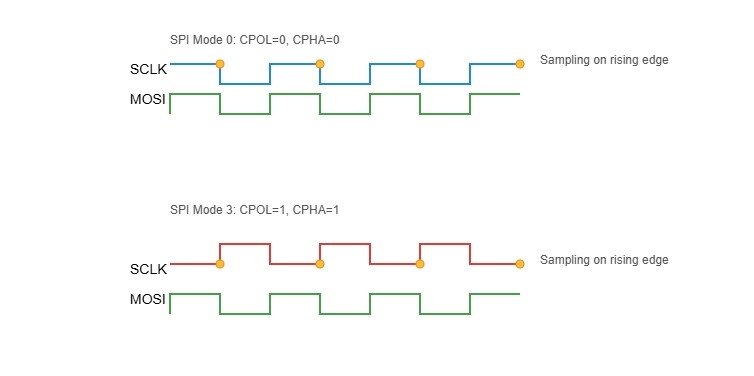
SPI modes are defined by two settings: CPOL (clock polarity) and CPHA (clock phase). These control how the clock signal behaves and when data is sampled, creating four modes: Mode 0, Mode 1, Mode 2, and Mode 3. Here’s how they work:
- CPOL sets the clock’s idle state:
- CPOL=0: Clock idles low (starts at 0).
- CPOL=1: Clock idles high (starts at 1).
- CPHA sets when data is sampled:
- CPHA=0: Data sampled on the first clock edge (rising if CPOL=0, falling if CPOL=1).
- CPHA=1: Data sampled on the second clock edge (falling if CPOL=0, rising if CPOL=1).
The Four SPI Modes
- Mode 0: CPOL=0, CPHA=0 – Clock idles low, data sampled on rising edge.
- Mode 1: CPOL=0, CPHA=1 – Clock idles low, data sampled on falling edge.
- Mode 2: CPOL=1, CPHA=0 – Clock idles high, data sampled on falling edge.
- Mode 3: CPOL=1, CPHA=1 – Clock idles high, data sampled on rising edge.
Mode 0: Common for LCDs
Mode 0 (CPOL=0, CPHA=0) is the most common for LCDs. The clock starts low, and data is sampled on the rising edge (when the clock goes from low to high). This timing aligns well with many LCD controllers like ST7735 or ILI9341. Here’s why it matters:
- Data is stable when the clock rises, making it reliable for LCDs.
- Most microcontrollers default to Mode 0, simplifying setup.
Selecting the Correct Mode
To pick the right SPI mode, you need to match your microcontroller’s settings to the LCD’s requirements. Here’s how:
- Check the Datasheet
Find your LCD controller’s datasheet (e.g., ST7735, ILI9341). Look for a section on SPI or timing. It’ll specify CPOL and CPHA or directly state the mode (usually Mode 0 for LCDs). - Common LCD Controllers
- Set Your Microcontroller
In your code or hardware settings, configure the SPI module. For example:- Arduino:
SPI.beginTransaction(SPISettings(speed, MSBFIRST, SPI_MODE0)); - Adjust CPOL and CPHA to match the datasheet.
- Arduino:
- Fix Mode Mismatches
If the LCD shows garbage or nothing:- Double-check the datasheet—mode details can be buried.
- Test other modes (0–3) if unsure, but start with Mode 0.
- Verify clock speed (e.g., 8 MHz max for some LCDs).
If your LCD is not displaying properly, such as showing corrupted data or blank screens, the issue may be a mode mismatch. You can resolve this by adjusting the SPI mode configuration in your microcontroller’s software.
Always consult the LCD controller datasheet to confirm the required SPI mode.
Many common LCD controllers support Mode 0 or Mode 3.
- Mode 0
- Clock: Low idle, rising edge triggers sample
- MOSI: Data set up before rising edge
- Sample: On rising edge
- Mode 1
- Clock: Low idle, rising edge shifts data
- MOSI: Data set up after rising edge
- Sample: On falling edge
- Mode 2
- Clock: High idle, falling edge triggers sample
- MOSI: Data set up before falling edge
- Sample: On falling edge
- Mode 3
- Clock: High idle, falling edge shifts data
- MOSI: Data set up after falling edge
- Sample: On rising edge
How to Initialize Firmware and Send Commands to an SPI LCD?

To work with an SPI LCD, you need to initialize its firmware and send commands or data using the MOSI (Master Out Slave In) line. The C/D line (Command/Data line) plays a key role by telling the LCD whether you’re sending a command (like setting resolution) or data (like pixel colors). This section explains how to set up the LCD with initialization sequences and send display data, including a pseudocode example and tips to avoid common issues. Incorrect setup can result in a blank screen or garbled output.
How to Write Initialization Sequences for an SPI LCD?
Writing initialization sequences involves sending a series of commands through MOSI to configure the LCD’s settings, such as resolution and color format. The C/D line distinguishes commands from data: low (0) for commands, high (1) for data. Follow these steps:
- Set C/D Low for Commands
Set the C/D line to 0 to indicate a command, like configuring the display mode. - Send Command via MOSI
Use the SPI interface to transmit the command byte. For example,0x2Amight set the column address. - Set C/D High for Data
Switch C/D to 1 to send data bytes that follow the command, such as specific resolution values. - Repeat for All Commands
Typical LCDs require multiple commands—reset, sleep out, color mode, etc. Refer to the LCD datasheet for the exact sequence.
Code Example
					// Code for initializing an SPI LCD
spi_begin();
set_C_D_low();  // Command mode
spi_send(0x01);  // Software reset
delay(100);      // Wait for reset

set_C_D_low();
spi_send(0x11);  // Sleep out
delay(10);

set_C_D_low();
spi_send(0x3A);  // Set color mode
set_C_D_high();
spi_send(0x05);  // 16-bit RGB565

set_C_D_low();
spi_send(0x29);  // Display on
spi_end();
Command vs. Data Writes
- Commands (C/D=0): Instructions to control the LCD, e.g., setting modes or memory addresses.
- Data (C/D=1): Values like pixel colors or text characters.
A frequent error is mismanaging the C/D line—ensure it’s set correctly for each byte sent.
How to Send Display Data to an SPI LCD?
Sending display data means transmitting pixel data or text via MOSI to update the LCD screen, with the C/D line set to high for data mode. The bit-depth (e.g., 16-bit RGB565 or 24-bit RGB) determines how much data each pixel requires(Color Depth Processing for LCD Panels with LED Backlighting). Here’s how to do it:
- Set Memory Address
Use commands to define the display area (e.g., row and column ranges) before sending data. - Set C/D High for Data
Switch C/D to 1 to indicate data transmission. - Send Pixel Data
Transmit color data for each pixel in the correct format. For 16-bit RGB565, send 2 bytes per pixel; for 24-bit RGB, send 3 bytes. - Understand Bit-Depths
- 16-bit RGB565: Uses 5 bits for red, 6 for green, 5 for blue—common for small displays due to faster transfer.
- 24-bit RGB: Full 8 bits per color—richer colors but slower due to more data.
Example: Sending a Red Pixel in RGB565
- Red in 16-bit RGB565 is
0xF800. - Send as two bytes:
0xF8, then0x00.
How Does the SPI Protocol Work for LCD Communication?

The Serial Peripheral Interface (SPI) protocol is widely used to connect microcontrollers to peripherals like LCDs. It’s a synchronous, full-duplex communication system that relies on a clock signal to coordinate data transfer. Below, we dive into how SPI’s full-duplex capability works and compare the 3-wire and 4-wire configurations for LCDs(Parallel vs Serial: Understanding Communication Methods).
Full-Duplex Mechanics
SPI’s full-duplex capability allows a microcontroller to send and receive data simultaneously. This is achieved using four key lines:
- MOSI (Master Out Slave In): Carries data from the microcontroller to the LCD.
- MISO (Master In Slave Out): Carries data from the LCD back to the microcontroller.
- SCLK (Serial Clock): A clock signal generated by the microcontroller to synchronize the data transfer.
- CS (Chip Select): Selects the specific LCD device for communication.
In a full-duplex setup, data flows in both directions during the same clock cycle. For example, while the microcontroller sends a command to the LCD via MOSI, it can simultaneously receive status information from the LCD via MISO. This simultaneous operation is synced by the SCLK signal, ensuring both devices stay in step.
When Is MISO Used in LCD Communication?
While full-duplex is possible, many LCDs don’t fully utilize MISO because they primarily receive data (e.g., display commands or pixel data) rather than send it. However, MISO becomes useful in specific scenarios:
- Status Polling: Some LCDs send status bytes back to the microcontroller via MISO, indicating if the display is busy, ready, or has encountered an error. For instance, you might send a “check status” command on MOSI and receive a response like “display ready” on MISO in the same cycle.
- Reading Data: Advanced LCDs allow the microcontroller to read data, such as pixel values or configuration registers, over MISO. This is less common in basic displays but valuable for debugging or dynamic updates.
If an LCD doesn’t support these features, the MISO line can often be left unconnected, simplifying the setup.
3-Wire vs. 4-Wire SPI for LCDs
SPI for LCDs comes in two main flavors: 3-wire and 4-wire. Each has distinct characteristics that affect how they’re used with LCDs.
- 3-Wire SPI
- Structure: Uses a single bidirectional data line (often labeled SDA) for both sending and receiving data, plus SCLK and CS.
- Operation: Half-duplex—data can only move in one direction at a time. The microcontroller switches between sending and receiving modes as needed.
- Pros: Saves a pin, making it ideal for devices with limited I/O.
- Cons: Slower due to the lack of simultaneous data transfer, and managing bidirectional communication can add complexity.
- 4-Wire SPI
- Structure: Uses separate MOSI and MISO lines for data, plus SCLK, CS, and often a C/D (Command/Data) line.
- Operation: Full-duplex—data can flow in both directions at once. The C/D line specifies whether the data on MOSI is a command (e.g., “set resolution”) or display data (e.g., pixel values).
- Pros: Faster and simpler to manage, especially with the C/D line distinguishing command and data phases.
- Cons: Requires more pins than 3-wire SPI.
Why 4-Wire Is Preferred for LCDs with C/D Lines
The 4-wire SPI setup is favored for LCDs because of its efficiency and clarity:
- C/D Line Advantage: The dedicated Command/Data line eliminates the need for extra protocol steps to indicate what type of data is being sent. For example, you can send a command to clear the screen followed immediately by pixel data without additional signaling.
- Full-Duplex Potential: While not always used, the separate MOSI and MISO lines allow for simultaneous communication, which is handy for status polling or data reading.
- Compatibility: Most SPI-enabled LCD modules are designed with 4-wire support, making it a standard choice.
Advanced Integration in Embedded Systems

Graphics and Font Rendering
Rendering graphics and fonts on an SPI-connected LCD involves efficiently transferring pixel data to the display. Here’s how it works:
- Sending Pixel Maps: To display images, you send a pixel map—an array of color values representing each pixel. For a color LCD, a common format is RGB565, which uses 16 bits per pixel. For a 240×320 resolution display, this translates to approximately 150 KB per frame (240 × 320 × 2 bytes). Since SPI communication is serial and microcontrollers have limited memory, you typically break the data into smaller chunks, such as individual lines or blocks, and send them sequentially. This approach prevents memory overflow and ensures smooth rendering.
- Fonts and Shapes: Text rendering relies on pre-defined font bitmaps—small pixel arrays for each character. To display a character, you send its corresponding pixel data to the LCD. For shapes like lines or circles, you calculate the pixel coordinates programmatically and send the appropriate color values. Many embedded systems use libraries to simplify this, but manual implementation can optimize performance for specific use cases.
- Memory Requirements: Graphics-intensive applications demand significant memory. For example, double buffering—where one frame is shown while the next is prepared—requires two frame buffers, doubling the memory need to 300 KB for a 240×320 display in RGB565. In resource-constrained systems, this may exceed onboard RAM, necessitating external memory or optimization techniques like partial screen updates (only refreshing changed areas). Reducing color depth to 8 bits per pixel can cut memory usage in half, though it may compromise visual quality.
Balancing memory, processing power, and display quality is critical for effective graphics rendering in embedded systems.
DMA and Performance Optimization
Direct Memory Access (DMA) enhances LCD performance by offloading data transfers from the CPU, improving refresh rates and system efficiency(How Does DMA Improve Display Updates in Embedded Systems?).
- How DMA Enhances Refresh Rates: DMA enables the SPI peripheral to move data directly from memory to the LCD without CPU involvement. This parallelism allows the CPU to focus on tasks like preparing the next frame or handling inputs while the current frame is transmitted. For graphics-heavy applications, such as animations, this can significantly boost refresh rates, making updates smoother and more responsive.
- Code for DMA-Based Data Transfers: Below is an example of setting up a DMA transfer for SPI communication with an LCD:
					// Configure DMA for SPI transfer
DMA_SetSourceAddress(frameBuffer);         // Source: frame buffer in memory
DMA_SetDestinationAddress(SPI_DATA_REGISTER); // Destination: SPI peripheral
DMA_SetTransferSize(frameSize);            // Size of data to transfer
DMA_Enable();                              // Start the transfer

// CPU can perform other tasks during transfer
prepareNextFrame();

// Wait for DMA to finish
while (!DMA_TransferComplete());
In this setup, the DMA controller handles the data transfer in the background, freeing the CPU for concurrent operations.
- Optimization Tips: To maximize performance, use DMA burst modes for faster transfers, set the SPI clock to the highest rate supported by both the microcontroller and LCD, and ensure memory alignment for efficient DMA access. In practice, DMA can double or triple frame rates, making it essential for real-time graphics.
How to Achieve Advanced SPI LCD Integration in Embedded Systems?
Advanced SPI LCD integration in embedded systems involves rendering pixel maps, fonts, and shapes via SPI, using DMA to improve LCD refresh rates, and integrating SPI-based touch controllers. Manage memory requirements and bus contention for seamless performance(How Can You Create Custom Characters on an Character LCD?).
In applications like interactive dashboards, pixel maps and fonts create dynamic visuals, while DMA ensures fast updates. SPI-based touch controllers share the SPI bus, requiring prioritization to prevent bus contention. Below, we explore graphics rendering, performance optimization, and touch integration.
The table below outlines memory requirements for graphics tasks:
| Graphics Task | Memory Needed | Example Use Case |
|---|---|---|
| Pixel Maps | 50-200 KB | Full-screen images |
| Fonts | 10-50 KB | Text displays |
| Shapes | 5-20 KB | Icons, simple graphics |
How to Render Graphics and Fonts on an SPI LCD?
To render graphics on an SPI LCD, transmit pixel maps, fonts, or shapes via SPI by setting the C/D line high for data. Memory requirements depend on the task: pixel maps for a 320×240 display at 16-bit need 153 KB, while fonts and shapes use less.
In projects like wearable displays, pixel maps display images, but large memory requirements can strain small microcontrollers. Fonts enable text updates, and shapes like icons save space. Preload data into RAM or flash to avoid delays.
Here are steps to send graphics:
- Store pixel maps or fonts in memory (e.g., 16-bit RGB565).
- Set C/D line high for data mode.
- Send pixel data or font bytes via MOSI.
- Check memory usage to prevent overflows.
How to Use DMA for SPI LCD Performance Optimization?
Direct Memory Access (DMA) boosts LCD refresh rates by transferring pixel data directly from memory to the SPI peripheral, reducing CPU load. This enables smooth updates, supporting rates up to 25 MHz for graphics-heavy displays.
In applications like navigation systems, DMA ensures fast LCD refresh rates (e.g., 60 FPS for 240×320). Without DMA, CPU bottlenecks slow updates. Verify the microcontroller supports DMA and configure it for efficient transfers.
When should you consider alternative display interfaces?
Switch away from SPI when your screen’s resolution or refresh rate exceeds SPI’s high-resolution capability or when the number of I/O lines in a parallel/RGB bus is acceptable compared to SPI’s reduced pin count advantage. High‑speed parallel or RGB interfaces handle larger data volumes more efficiently.
In one wearable project, SPI at 25 MHz filled a 320×240 panel at 30 FPS. Upgrading to a 7″ 800×480 display, full‑screen redraws slowed to 5 FPS over SPI, highlighting the speed-complexity limit. Moving to a 16‑bit parallel bus at 50 MHz restored 60 FPS. Later, when integrating a 1080p panel, we evaluated MIPI compatibility and LVDS integration to meet bandwidth needs(Exploring LVDS and MIPI Interface).
| Interface | Max Throughput | Pin Count | Error Checking | Best For |
|---|---|---|---|---|
| SPI | 25 MHz | 4–5 | None | Small/mid panels ≤ 320×240 |
| Parallel Bus | 50 MHz+ | 8–16 | Optional | Mid‑res up to 800×480 |
| RGB Interface | 80 MHz+ | 16–24 | Optional | High‑speed color graphics |
| MIPI D‑PHY | Gbps range | 4–8 lanes | CRC optional | High‑res mobile/UHD panels |
| LVDS | 1 Gbps+ | 4–6 pairs | CRC optional | Large‑format displays |
When should you switch from SPI to parallel or RGB interfaces?
You switch when your display’s data rate needs exceed SPI’s 25 MHz limit, or when extra pins are available to support wider buses for smoother full‑screen updates.
On a handheld meter, SPI handled a 128×64 screen fine. Upgrading to a 5″ 800×480 TFT, SPI updates lagged. We added a 16‑bit parallel bus, doubling throughput and eliminating flicker. This change addressed the speed-complexity trade‑off and leveraged available MCU pins without overloading software.
| Aspect | SPI (25 MHz) | Parallel (50 MHz) | RGB (80 MHz) |
|---|---|---|---|
| Full‑frame redraw | 30 FPS max | 60 FPS max | 120 FPS max |
| Pin usage | reduced pin count | 10–16 | 16–24 |
| Bus complexity | Simple | Moderate | High |
How to Transition to Advanced Protocols like MIPI or LVDS?
For high-resolution displays (e.g., 1080p), MIPI (Mobile Industry Processor Interface) and LVDS (Low-Voltage Differential Signaling) outperform SPI, parallel, and RGB interfaces. These protocols handle massive data with low power consumption and robust signal integrity.
- MIPI:
- Overview: A high-speed serial protocol for mobile and embedded displays.
- Benefits: Supports 4K resolutions, low power use, and long-distance communication (up to 1 meter).
- Drawbacks: Needs specialized controllers and complex software stacks.
- Use Case: Smartphones, tablets, or high-end embedded displays.
- LVDS:
- Overview: Uses differential signaling for fast, noise-resistant data transfer.
- Benefits: Handles high resolutions (e.g., 1920×1080) with minimal electromagnetic interference.
- Drawbacks: Requires dedicated hardware and more pins than MIPI.
- Use Case: Large monitors, industrial displays.
In practice, MIPI is common in compact, high-res devices, while LVDS suits industrial systems. Always check the datasheet for protocol support and test with a reference design to avoid surprises.
To choose between MIPI, LVDS, or others:
- Check display resolution: MIPI or LVDS for 1080p+; SPI or parallel for 480p or less.
- Assess microcontroller support: Ensure your MCU supports MIPI or LVDS controllers.
- Evaluate power budget: MIPI is more power-efficient for portable devices.
- Consider distance: LVDS excels for longer connections (e.g., 5 meters).
Related Articles:
Should You Use Custom Display Layers or HALs for LCD Integration?
How Do You Handle Byte-Order (LSB vs. MSB First) in Page-Mode Writes?
What Is the Difference Between COG and COB LCD?
Why Do LCDs Use AC Instead of DC?
Why Do Some LCD Modules Require a Negative Voltage for Contrast Adjustment?
FAQ
What should I do if my SPI LCD shows nothing on the screen?
Check all connections and confirm that the CS line is controlled correctly. Make sure your firmware sends the correct initialization commands and that the SPI mode matches the LCD’s requirements.
How can I connect both a touch panel and an LCD to the same SPI bus?
Use separate chip select (CS) lines for each device and manage access in your firmware. Always prioritize touch events if quick user response is needed.
Can I use SPI for high-resolution or video displays?
SPI works best for small-to-medium screens and static or lightly animated graphics. For video or high-resolution applications, consider parallel, RGB, or MIPI interfaces for higher bandwidth.
What happens if the SPI mode or clock speed does not match the LCD’s datasheet?
A mismatch can cause flickering, no display, or corrupted graphics. Always set the SPI mode and speed as specified in the LCD controller’s datasheet.
Can SPI handle color depth changes during LCD operation?
Adjust color depth (e.g., 16-bit RGB565 to 24-bit RGB) by sending new initialization commands via MOSI. Check the LCD datasheet for supported formats and update firmware accordingly.