To handle byte-order in page-mode writes, you must match the device’s endianness and bit-order. This ensures each byte or bit is written in the way the memory or display expects. Start by checking if the device reads LSB-first or MSB-first data.
When your system and the device use different orders, reverse the bytes or bits before sending. Use simple code functions or hardware settings where possible. If the hardware doesn’t allow changes, apply bit-level manipulation in software.
Page-mode writes must also follow memory constraints. Align the data block to the page size and start address. Avoid crossing page boundaries without restarting the write cycle. This helps keep the data correct and complete.
These steps work together. You organize data for the page, then arrange it by bit and byte order. If you miss any part, the result may be unreadable or ignored by the device.
What Are the Fundamentals of Byte Ordering (Endianness)?
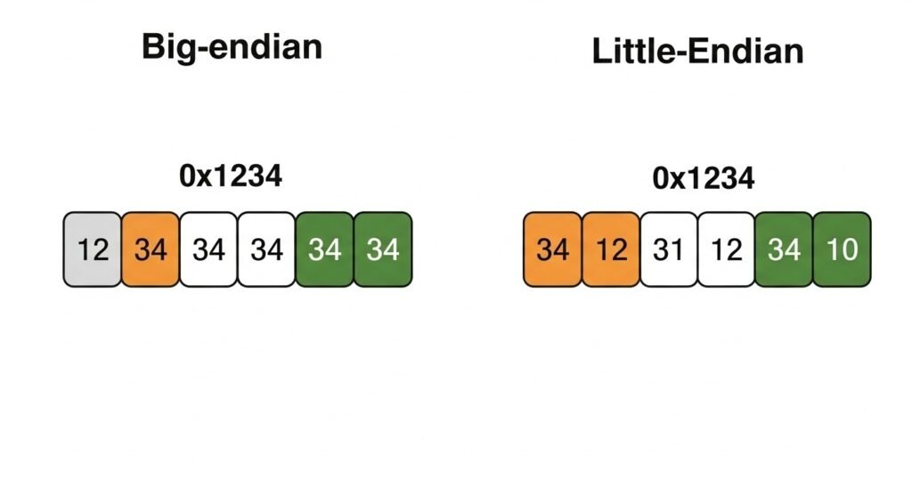
Byte ordering, or endianness, is how computers arrange bytes in memory for multi-byte data like integers. There are two types: big-endian and little-endian. In big-endian, the most significant byte (MSB) comes first. In little-endian, the least significant byte (LSB) comes first. This difference affects how systems store and read data. It can cause issues when devices or programs use different endianness, making it a key concept for anyone working with computers or networks.
This matters in real projects. For instance, x86 processors, found in many computers, use little-endian. Network protocols, like those for the internet, often use big-endian. I once worked on a project where data from a sensor (big-endian) was misread by a little-endian processor until we swapped the bytes. Knowing endianness helps you avoid these mix-ups and ensures data moves smoothly between systems.
Here’s a quick look at the difference:
- Big-endian: Stores
0x12345678as12 34 56 78. - Little-endian: Stores
0x12345678as78 56 34 12.
Think of it like reading a number: big-endian goes left to right, while little-endian goes right to left.
What Is Byte Order?
Byte order, also called endianness, is the way bytes are placed in memory for multi-byte values. In big-endian, the most significant byte (MSB) goes to the lowest memory address. In little-endian, the least significant byte (LSB) goes first. This choice changes how data looks in memory and can lead to errors if not handled right.
Take a 32-bit number like 0x12345678. In a big-endian system, it’s stored as 12 34 56 78 across four memory addresses. In a little-endian system, it’s 78 56 34 12. I’ve seen this cause headaches in embedded projects—like when a device sent data in big-endian, but the software expected little-endian. Checking the byte order saved the day.
Here’s the layout:
- Big-endian:
- Address 0:
0x12 - Address 1:
0x34 - Address 2:
0x56 - Address 3:
0x78
- Address 0:
- • Little-endian:
- Address 0:
0x78 - Address 1:
0x56 - Address 2:
0x34 - Address 3:
0x12
- Address 0:
Imagine memory as a row of boxes. Big-endian fills them from the big end; little-endian starts with the small end.
How Do You Determine and Match Endianness?
You need to know a system’s endianness to work with its data correctly. Check the system architecture details in its device datasheet or run a test with code. This prevents mistakes when connecting devices or sending data across networks.
In one project, I had to figure out a device’s endianness. The datasheet wasn’t clear, so I wrote a quick test. I stored a number like 0x12345678 and checked the first byte in memory. If it was 0x78, the system was little-endian; if 0x12, it was big-endian. Here’s a simple C example:
					#include <stdio.h>

int main() {
    union {
        unsigned int num;
        unsigned char bytes[4];
    } test;
    test.num = 0x12345678;
    if (test.bytes[0] == 0x78) {
        printf("Little-endian\n");
    } else if (test.bytes[0] == 0x12) {
        printf("Big-endian\n");
    }
    return 0;
}
If endianness doesn’t match, use byte-swapping. For example, to flip 0x12345678 to 0x78563412, you can write a function like this:
					unsigned int swap_bytes(unsigned int x) {
    return ((x & 0xff000000) >> 24) |
           ((x & 0x00ff0000) >> 8) |
           ((x & 0x0000ff00) << 8) |
           ((x & 0x000000ff) << 24);
}
This swaps the bytes to match the other system’s order.
What Is Bit Ordering (Serialization) in Communication Protocols?
Bit ordering, or serialization order, defines how bits are arranged and transmitted over communication lines. There are two common formats: MSB-first (Most Significant Bit first) and LSB-first (Least Significant Bit first). The order determines whether the highest or lowest value bit is transmitted first. Different protocols follow different bit ordering rules. For example, SPI usually transmits MSB-first, I2C also uses MSB-first, while some UART implementations may vary or be configurable.
Incorrect handling of bit order leads to misinterpreted commands, data corruption, and communication breakdown, especially in embedded LCD systems and sensor interfacing.
Bit Ordering Across Communication Protocols
| Protocol | Default Bit Order | Configurability |
|---|---|---|
| SPI | MSB-first | Some controllers allow LSB-first |
| I2C | MSB-first | Generally fixed |
| UART | Often LSB-first | Depends on implementation |
What Is Bit Order?
Bit order refers to the sequence of bit transmission in a byte. In MSB-first transmission, the most significant bit is sent first. In LSB-first, the least significant bit goes first. For an 8-bit value 0b10110010, MSB-first sends 1 first, while LSB-first sends 0 first.
Protocols are designed with a default order. For example, SPI’s MSB-first format aligns with most memory and register maps. In UART, some systems default to LSB-first, where the lowest-value bit leads.
In a display module using SPI communication, failing to follow the correct bit order results in distorted colors, misread commands, or incomplete frames.
Bit Order Visualization: MSB vs. LSB Transmission
					Byte: 0b11001001
MSB-first: 1 -> 1 -> 0 -> 0 -> 1 -> 0 -> 0 -> 1
LSB-first: 1 -> 0 -> 0 -> 1 -> 0 -> 0 -> 1 -> 1
How Can You Reverse Bit Order?
Reversing bit order is essential when interfacing two systems with mismatched transmission formats. You can achieve this through bit-reversal algorithms in software or by configuring hardware registers in some microcontrollers.
Bit-Reversal in C
					unsigned char reverseBits(unsigned char b) {
    b = (b & 0xF0) >> 4 | (b & 0x0F) << 4;
    b = (b & 0xCC) >> 2 | (b & 0x33) << 2;
    b = (b & 0xAA) >> 1 | (b & 0x55) << 1;
    return b;
}
This function flips the bits from MSB to LSB or vice versa. It is useful when the peripheral expects a different bit order.
For performance-critical systems, reversing bits in hardware is faster. Many MCUs with SPI or UART modules include control registers to set the bit order automatically.
Software vs. Hardware Bit Reversal
| Method | Use Case | Pros | Cons |
|---|---|---|---|
| Software | Cross-platform, portable | Flexible, simple to debug | CPU overhead, slower |
| Hardware | High-speed communication, MCU-specific | Fast, efficient | Requires supported hardware |
Why Does Bit Order Matter in Embedded LCD Systems?
Bit order directly affects how an LCD controller interprets data(What is an LCD controller board?). For example, if the controller expects MSB-first and receives LSB-first, the command will be misread, potentially causing no display, incorrect characters, or color errors.
In embedded LCD systems using UART or SPI, always consult the datasheet. Some allow bit order settings, others require you to reverse bits manually before transmission.
LCD System Configuration: Bit Order Matching
| Interface Type | Typical Bit Order | Adjustment Method |
|---|---|---|
| SPI | MSB-first | SPI control register |
| UART | LSB-first | Code-based bit reversal |
| I2C | MSB-first | Fixed, match in software |
How Can You Structure Page-Mode Writes with Correct Ordering?
Page-mode writing requires organizing data to match the page size and bit/byte order of memory devices like EEPROMs or flash. Data must be written with proper alignment, meaning both start address and data block length should fit within the defined page size. Additionally, in systems where multi-byte values are used, their endianness must match the storage or communication expectations, or the values will be misread or corrupted.
When page-mode write operations ignore correct ordering, the result may include overwritten bytes, incomplete transactions, or garbled output. Systems interfacing with LCD modules, sensor buffers, or embedded storage often rely on strict data and byte alignment, especially when operating over I2C or SPI buses.
Aligned Write Table: Page Size vs. Start Address
| Page Size | Aligned Address | Misaligned Example | Result |
|---|---|---|---|
| 64 bytes | 0x0000, 0x0040 | 0x0021 | Write spills across pages |
| 128 bytes | 0x0100, 0x0180 | 0x0111 | Extra write cycles required |
What Is Data Organization in Pages?
Memory devices typically organize storage in fixed-size pages, such as 32, 64, or 128 bytes. Page-mode write operations must begin at the start of a page and should not cross a page boundary without a new write cycle. Writing across boundaries leads to partial writes or data corruption.
To ensure consistent behavior, developers align the start address to the page boundary and pad or trim the data to match the page size. For instance, writing 48 bytes starting at address 0x0020 on a 64-byte page results in an overflow into the next page, unless handled carefully.
In LCD modules or EEPROM configurations, this level of control ensures correct frame updates, font storage, or image rendering.
Byte and Bit Considerations for Page Writing
| Condition | Alignment Required | Notes |
|---|---|---|
| Single-byte writes | No | Safer, slower for bulk updates |
| Multi-byte values | Yes | Watch for endianness mismatches |
| Structured arrays | Yes | Align to both element and page size |
What Happens in a Real EEPROM Page Write Example?
Let’s walk through a 64-byte EEPROM using SPI for a full-page write. The key is ensuring proper alignment and byte ordering for multi-byte data like uint16_t or uint32_t values.
- Start at aligned address: e.g., 0x0080 (64-byte boundary)
- Organize data block: Ensure data fits in 64 bytes. Group multi-byte values.
- Convert endianness: If needed, reverse byte order to match EEPROM expectations.
- Initiate SPI transfer: Use CS (Chip Select), then send instruction, address, and data.
- Wait for write cycle: Monitor status register or delay as needed.
Example Write Code (C-style Pseudocode)
					void writeEEPROMPage(uint16_t startAddr, uint8_t* data) {
    selectEEPROM(); // Activate CS
    sendByte(WRITE_COMMAND);
    sendByte((startAddr >> 8) & 0xFF); // MSB of address
    sendByte(startAddr & 0xFF);        // LSB of address
    for (int i = 0; i < 64; i++) {
        sendByte(data[i]); // Byte order must match EEPROM's expectation
    }
    deselectEEPROM();
    waitForWriteCycle();
}
If the EEPROM is MSB-first and your system is LSB-first, reverse the byte order before calling sendByte().
Bit/Byte Handling Chart
| Data Type | System Endian | EEPROM Expectation | Action Needed |
|---|---|---|---|
| uint16_t | LSB-first | MSB-first | Reverse before write |
| uint32_t | MSB-first | MSB-first | No change |
| Custom Cmd | Mixed | Defined by device | Consult datasheet |
How to Handle Multi-Byte Values with Different Endianness?
When writing structures or buffers containing multi-byte data, you must detect whether the memory device stores bytes in MSB-first or LSB-first order. Mismatches cause data to appear reversed or corrupted.
Use utility functions to convert byte order before writing. Alternatively, some systems provide compiler macros or intrinsics for endian conversion.
Reversing uint16_t for MSB-first EEPROM
					uint16_t val = 0x1234;
uint8_t hi = (val >> 8) & 0xFF;
uint8_t lo = val & 0xFF;
sendByte(hi); // Send MSB first
sendByte(lo); // Then LSB
Endian Conversion Reference Table
| Input Format | Target Format | Conversion Required | Tool |
|---|---|---|---|
| LSB-first | MSB-first | Yes | Bitwise operations |
| MSB-first | LSB-first | Yes | Manual or built-in API |
| Native Match | Native Match | No | Direct transfer |
How Can You Configure Communication Protocols for Correct Byte/Bit Order?
To ensure accurate data transmission, communication protocols must be configured with the correct byte and bit order. Many protocols, like SPI, I2C, and UART, offer options to set bit transmission order (e.g., MSB-first or LSB-first) and expect data in specific byte orders depending on the connected device. If hardware allows it, these settings are done using registers or driver functions such as SPI.setBitOrder() in platforms like Arduino. When hardware doesn’t allow this adjustment, you must rely on software-level byte or bit reversal before transmission(How Should You Drive Backlight in an Embedded LCD Display?).
Incorrect configuration results in inverted commands, garbled values, or LCD misbehavior in embedded systems. Understanding both protocol capabilities and device expectations is key.
Byte/Bit Order Support Across Protocols
| Protocol | Bit Order Configurable | Byte Order Affected | Common Setting |
|---|---|---|---|
| SPI | Yes (e.g., setBitOrder) | Yes (handled in software) | MSB-first |
| I2C | No | Yes (manual packing) | MSB-first |
| UART | Rarely | Yes (handled manually) | LSB-first or variable |
What Are SPI, I2C, and UART Protocol Settings?
SPI allows bit order configuration, typically through functions like SPI.setBitOrder(MSBFIRST) on platforms like Arduino or by modifying control registers directly on microcontrollers. This sets whether the most or least significant bit is transmitted first. Devices like LCD modules, EEPROMs, or flash chips may require a specific setting.
I2C usually follows MSB-first transmission, and its bit order is not adjustable. Data arrangement must be handled in software. UART protocols differ—some send LSB-first, and most do not allow bit order configuration. Instead, you need to manage byte composition before writing.
SPI Bit Order Configuration in Arduino
					SPI.begin();
SPI.setBitOrder(MSBFIRST); // or LSBFIRST
SPI.transfer(myByte);
This ensures that the SPI hardware sends bits in the correct sequence to match the peripheral’s expectations.
Protocol Configuration Summary Table
| Platform | Configuration Method | Affected Order | Tools/Functions |
|---|---|---|---|
| Arduino (SPI) | SPI.setBitOrder() | Bit order | SPI library |
| STM32 (SPI) | CR1 register (LSBFIRST) | Bit order | HAL or direct register |
| UART (general) | Rare direct control | Byte/bit | Software buffer handling |
How Do You Handle Inflexible Hardware?
Some devices don’t allow configuration of bit order. In such cases, developers must rely on software-level bit reversal before sending or after receiving data. This applies often in I2C slave devices, fixed-format LCD modules, or legacy UART interfaces.
When sending uint16_t or uint32_t data to a device that expects a different byte or bit order, use helper functions to manually rearrange the bits or bytes. These can include bitwise operations, lookup tables, or bit reversal macros.
Bit Reversal Function
					uint8_t reverseBits(uint8_t b) {
    b = (b & 0xF0) >> 4 | (b & 0x0F) << 4;
    b = (b & 0xCC) >> 2 | (b & 0x33) << 2;
    b = (b & 0xAA) >> 1 | (b & 0x55) << 1;
    return b;
}
Use this when a device expects MSB-first but your system outputs LSB-first.
Software-Level Adjustment Reference Table
| Problem | Software Solution | Use Case Example |
|---|---|---|
| Bit order mismatch | Bit reversal function | SPI LCD with fixed MSB-first input |
| Byte order mismatch | Manual shifting or unions | EEPROM page write |
| Struct field mismatch | Memory copy with reorder | UART sensor payload |
How Does Byte and Bit Order Impact Embedded and LCD Systems?
Byte and bit order directly affect how data is interpreted and displayed in embedded systems, especially when working with LCD modules. In systems using UART, SPI, or I2C interfaces, a mismatch in the expected MSB/LSB ordering can lead to misaligned characters, garbled graphics, or broken commands. These issues arise when the display controller expects data in a different bit sequence or byte alignment than what the host microcontroller sends(What Are the Differences Between SPI and I2C for LCD Modules?).
Proper byte and bit manipulation ensures consistent and readable output across platforms, protocols, and architectures. In multi-endian environments, additional care is needed to preserve data meaning across different firmware builds and MCU types.
Byte and Bit Order in Embedded Interfaces
| Interface | Bit Order Used | Byte Order Considered | LCD Implication |
|---|---|---|---|
| UART | LSB-first | Yes | Reversed text or incorrect chars |
| SPI | MSB-first | Yes | Bit-shifted pixels, wrong colors |
| I2C | MSB-first | Yes | Misinterpreted register data |
How Does Bit Order Affect LCD Module Communication?
Many LCD modules using UART transmit and receive data LSB-first. If the microcontroller sends MSB-first, each byte will be misread, and the LCD might show inverted characters or ignore commands. In display systems using SPI, most modules expect MSB-first bit order, and failure to configure this correctly causes pixel data corruption.
To handle this, developers use either hardware configuration (like SPI.setBitOrder()) or bit reversal algorithms. Bitwise tools allow converting between LSB and MSB order.
Bit Alignment Fix for UART LCD
uint8_t correctByte = reverseBits(originalByte); // Ensure correct UART bit sequence
Use this before transmitting a byte to the LCD if the protocol sends LSB-first but the device expects MSB-first.
Common LCD Communication Mismatch Scenarios
| Scenario | Error Seen | Correction Method |
|---|---|---|
| LSB data sent to MSB LCD | Characters display incorrectly | Reverse bits before send |
| MSB SPI sent to LSB display driver | Inverted image or commands fail | Use SPI config or reverse |
| Struct data sent directly | Partial display data or glitch | Flatten and align bytes |
What Happens When Interfacing with Multi-Endian Systems?
When exchanging data across systems with different endianness, such as between a Little-Endian microcontroller and an MSB-first display controller, the same binary value may be interpreted differently. For example, 0x1234 sent from a Little-Endian MCU might arrive as 0x3412, resulting in incorrect rendering or command execution.
To avoid this, developers must detect the system’s endianness and convert multi-byte values accordingly before transmission or interpretation.
Cross-Platform Compatibility Technique
					uint16_t val = 0x1234;
uint8_t buffer[2];
// Convert to MSB-first for display
buffer[0] = (val >> 8) & 0xFF;
buffer[1] = val & 0xFF;
This guarantees that the LCD receives data in the expected order regardless of system architecture.
Portability Considerations Table
| Platform Pair | Endian Conflict | Solution |
|---|---|---|
| ARM MCU to LCD Controller | Yes | Byte swap before transmission |
| PC software to embedded | Often Yes | Serialization layer |
| Mixed vendor SoC + LCD | Yes | Use endian-neutral protocol |
Related Articles:
How is the Color Filter Layer Created in LCD Panels?
What Is a Frame Buffer and How Does It Work in Embedded Systems?
How Do Phase-Locked Loops Synchronize Timing in LCD Systems?
How Do Manufacturers Ensure Color Accuracy in Production?
How Is Hot-Swapping Handled in Modern LCD Controller Boards?
FAQ
What if the microcontroller and the device use different endianness?
You should reverse the byte order in software before sending the data to match the device’s expected format.
Can I use the same code for SPI and UART communication?
Not always. SPI and UART may use different bit orders, so you might need to adjust settings or reverse bits accordingly.
What happens if I write across a page boundary in EEPROM?
The device may wrap around and overwrite earlier data or skip the extra bytes, resulting in partial writes.
Do all LCD modules use MSB-first ordering?
No. Some use LSB-first, especially over UART. You must check the datasheet to know the exact requirement.
Is software bit reversal slow for real-time applications?
Yes, especially on slower microcontrollers. Use hardware settings or lookup tables if possible to improve speed.


