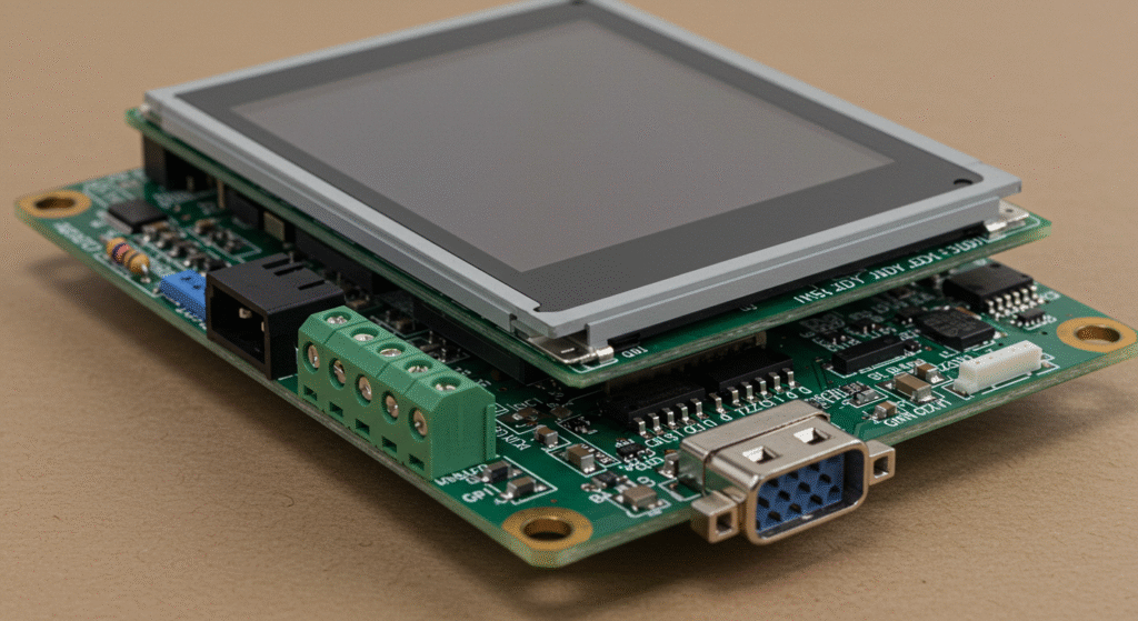
Hot swapping is inserting or removing components while the system runs. Modern embedded LCD controller boards use dedicated hot-swap controllers to limit inrush current and protect against faults (like overcurrent) during live insertion of an LCD panel or module.
Hot swapping allows an LCD module to be replaced without powering down the LCD system. This minimizes downtime and supports modular embedded LCD designs, allowing quick replacement of a live display panel through the LCD interface.
Modern hot-swap controllers include soft-start current ramping to gently charge an LCD panel’s capacitive load. They may also offer telemetry (e.g. via PMBus) for voltage/current monitoring and meet safety standards (e.g. UL/IEC certifications) for reliable operation.
HUA XIAN JING provides professional LCD module consulting service and 24 hours professional after-sales service. We provide customers with free design drawings and guidance on the development parameters of LCD modules. Contact us for professional LCD module technical support!
How Do Hot-Swap Controllers Protect LCD Systems?
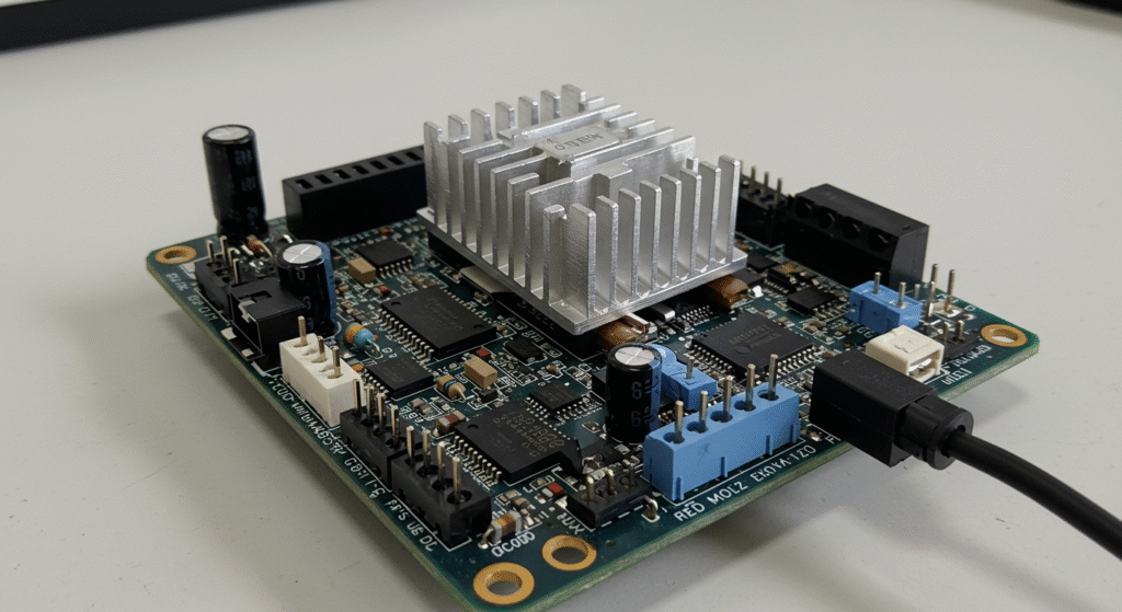
Hot-swap controllers in LCD systems manage the panel’s power-on sequence so that the display’s supply rails ramp up gently and are immediately shut off if a fault occurs. This prevents large current surges or shorts from reaching the LCD’s driver and backlight circuitry, avoiding damaging voltage spikes and overheating during hot-plug events.
In practice, engineers place a hot-swap IC in series with the LCD module’s power input on embedded display boards. The controller uses an integrated MOSFET to slowly charge the panel’s capacitive inputs (such as LED backlights and driver caps) and constantly monitors load current. If the display tries to draw too much current, the controller cuts off power in real time. This ensures that even high-capacitance LCD modules power up without browning out the bus or glitching the display interface, which is critical in industrial HMIs and other high-reliability screens.
- Inrush current control: The hot-swap controller limits the LCD module’s startup surge by controlling the series FET’s gate (soft-start), preventing a large instantaneous draw into the panel’s capacitive inputs. This soft‐start behavior mitigates voltage disturbances when the display is connected. In fact, as Texas Instruments notes, “LCD panels require inrush current control to prevent permanent system damages” during turn-on .
- Short-circuit/overcurrent protection: The controller continuously senses the LCD’s load current. If a short or overcurrent condition is detected on the display side, the IC immediately disconnects the output. This rapid fault response protects the LCD driver IC and backlight LEDs (and the host power rail) from excessive current that could otherwise damage them.
- Thermal shutdown: Many hot-swap ICs also monitor their own MOSFET temperature. If the pass transistor overheats (for example, due to sustained overload or high ambient heat), the controller disables its output until it cools. In an LCD system, this prevents prolonged thermal stress on the display’s power path or LEDs, safeguarding the module from heat-induced failure.
What Happens if an LCD System Lacks a Hot-Swap Controller?
Without a hot-swap controller, plugging in an LCD module can produce sudden current spikes and voltage dips. These transients may glitch or reset the display and even damage its driver or backlight circuitry due to the unmitigated surge.
- Voltage surges and brownouts: A cold-plugged LCD panel draws a large inrush current into its capacitive input, which can momentarily collapse (brown out) or spike the system voltage. This can reset or corrupt the display’s data and the host’s electronics when the panel is connected.
- Display panel damage: An uncontrolled power surge can exceed the LCD’s voltage or current ratings, risking blown LEDs, burned driver transistors, or other component failures. As one source warns, unprotected hot-plug events often lead to “equipment damage” and system faults.
- Power instability and downtime: Repeated hot-plugging under these conditions can trip upstream fuses or regulators, causing unexpected shutdowns of the display and host system. In practice, a lack of inrush control means designers may face frequent reboots or maintenance; Analog Devices notes that unprotected designs can suffer significant equipment damage and downtime
Inrush Current Control in Embedded LCD Systems
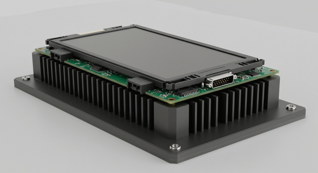
Embedded LCD systems manage inrush by using soft-start and current-limiting circuits in the power path. In practice, this means ramping up the panel’s supply rails (AVDD, VGH, VGL, etc.) slowly – for example, using a series MOSFET or resistor network to gradually apply voltage and keep the startup surge within safe limits.
In industry, LCD power ICs and load-switches often provide a controlled turn-on. Designers typically set a millisecond-range ramp or place a small NTC/resistor in series so that the panel’s internal capacitors charge over several milliseconds. Real systems will sequence the rails (AVDD first, then gate voltages) and target rise times (say 5–10 ms) such that peak currents stay on the order of 0.5–1 A per rail. This ensures the LCD module powers up cleanly without tripping protections or dragging down shared rails.
Capacitive Inrush: The main cause of inrush on an LCD controller board is the charging of its capacitive loads. The LCD module’s internal voltage pump caps and decoupling capacitors (on AVDD, VGH, VGL, etc.) look like a short at turn-on. For example, applying 3.3 V to a 47 µF cap can draw ~3.1 A. Many embedded LCD designs must handle tens of microfarads of capacitance, so without control the instantaneous current would be very high.
Soft-Start Methods: To mitigate this, designers insert controlled elements in series. A common solution is a series MOSFET (or “load switch”) whose gate is driven slowly via an RC or dedicated controller, causing the output voltage to ramp up over several milliseconds. Alternatively, a small series resistor or NTC thermistor can pre-charge the caps before being bypassed. Some LCD power ICs let engineers program a soft-start capacitor to lengthen the rise time. In effect, the panel’s supply is charged gradually rather than instantly, capping the inrush.
Foldback/Current Limiting: Many LCD DC/DC converters include overcurrent protection. For instance, a foldback limit reduces the output current if it detects a surge. In practice, this means if the LCD’s caps demand too much, the converter throttles or even hiccups. This protects the FETs and IC from damage, but it can also stall the startup if the caps remain too hungry. Designers must size soft-start and caps so the inrush stays just below the regulator’s limit.
Design Examples: In real LCD systems, thresholds and component sizes are chosen for safe startup. A typical small TFT might have ~10–20 µF on AVDD; with a 10 ms ramp to 15 V, that translates to an ~1.5 A average charge current. In fact, TI’s TPS65150 boost regulator shows measured inrush ~1.1 A on AVDD (to 15 V) and ~1.4 A on VGH (to 23 V) during turn-on. By tuning the soft-start or adding, say, a 10–20 Ω series resistor, designers can reduce the peak to a few hundred mA. In summary, embedded LCD modules use sequenced rails and soft-start components to stretch the capacitor charging time and limit surge current.
What If Inrush Control Is Ignored in an LCD System?
If inrush control is omitted, the startup surge can exceed component ratings or collapse the supply rails. In practice, an uncontrolled inrush may blow the MOSFET/regulator on the LCD’s power path or drag the 3.3 V/5 V bus down, causing devices to reset.
- Component Failure: A sudden amp-scale surge can exceed a FET’s safe operating area, overheating it or causing avalanche breakdown. Without current limiting, boost converter switches and panel drivers risk blowing out. Excessive inrush may trigger the converter’s protection, but if the threshold is exceeded, the FETs can be damaged.
- Rail Collapse: An uncontrolled spike will also pull down shared rails. TI notes that charging 100 µF without slew control produced a 6.88 A inrush that dragged a 3.3 V line to ~0.96 V. In an embedded LCD system, this would reset the MCU and peripherals or shut down other modules, since everything sees the same collapsed supply.
- Display Glitching: The panel may flicker or display artifacts. If the gate drivers never reach their target voltages, the LCD might show incomplete images or lock up mid-frame. Rapid voltage droops can scramble the display until the rails stabilize.
- Restart Loops (Hiccup): The power IC might enter hiccup mode. As Analog Devices describes, a rail driven too hard at startup can hit current limit, causing the converter to shut off and retry. The result is a cycle where the display never initializes – essentially a blink-off-blink-on loop – until power is cycled or inrush is tamed. Embedded LCD modules are particularly vulnerable to this, as their own boost pumps need a clean ramp to function.
Protection Features Ensuring Safe Hot-Swapping in LCD Systems
Hot-swap protection for LCD systems is provided by on-board current-limiter and power-switch features that isolate the LCD interface during faults. Overcurrent, short-circuit and thermal shutdown protections are built into modern hot-swap controllers or eFuse devices, ensuring that an LCD module can be inserted or removed without damaging the display or the host system.
In real-world LCD designs, engineers typically include a hot-swap controller (or intelligent eFuse) on the display’s power rails. This controller soft-starts the supply when the LCD is plugged in, then actively limits or disconnects the backlight and logic power if the current draw exceeds a set threshold. For example, many industrial panel monitors use a ramped turn-on sequence followed by a programmable overcurrent trip, so that a new LCD module can be hot-plugged without tripping upstream breakers or corrupting signals. This approach lets the system remain live during module swaps while preventing surges or shorts from propagating through the LCD interface.
Overcurrent Protection
Overcurrent protection uses a sense element (resistor or FET) to detect excessive current draw and then limit or cut off power. In practice, the hot-swap controller monitors the LCD’s supply current and compares it to a preset limit (typically on the order of 0.5–3 A for small LCD backlight rails. When the current exceeds this threshold, the controller either goes into active current limiting or disconnects the load. For instance, TI’s TPS25961 eFuse allows setting the current limit between 0.1 A and 2 A, while Analog Devices’ LTC4287 applies a dual-level scheme: a fast comparator set to about 3× the nominal limit immediately clamps sudden spikes, then an active feedback loop holds the current at the programmed level. In all cases the result is that any abnormal draw (e.g. backlight lamp short or LCD driver fault) is quickly isolated – the hot-swap FET stops conducting before the fault can drag down the supply or damage the LCD interface.Short-Circuit Protection
Short-circuit protection acts even faster to disconnect a hard fault on the LCD cable or connector. Modern hot-swap devices include very fast short-detect circuitry: a sudden VOUT collapse (to near 0 V) triggers an almost immediate shutoff. For example, TI’s TPS25961 eFuse reports a typical short-circuit response time of only ~5 µs. Similarly, LTC4287 instantly pulls the MOSFET gate to source when a direct short occurs, effectively opening the switch in nanoseconds. The design logic is the same as an electronic fuse: if the LCD panel or backlight line is shorted, the controller “trips” far faster than any manual fuse could, protecting the panel and backplane. In many designs the controller will then retry or latch off (depending on configuration), and a flag pin is asserted so the host knows a short happened. The LCD interface is thus kept safe – power is disconnected in under microseconds, before damage can happen.Thermal Shutdown
Thermal shutdown protection prevents overheating by turning off power when internal temperatures exceed a safe limit. Each hot-swap controller or power switch chip monitors its junction temperature and shuts off the output MOSFET if a threshold is reached. For many display power regulators this threshold is on the order of 150–170 °C (die temperature). For example, automotive-grade regulators guarantee shutdown around 170–180 °C, after which the device remains off until it cools by about 15–20 °C. In an LCD system this means that if an extended overload or external heat source drives the controller hot, it will cut power to the backlight/logic. Once the chip cools, normal operation resumes. Thermal shutdown thus protects embedded LCD modules from sustained thermal stress – even if over-current limiting kept them alive during a fault, thermal senses will shut the channel completely before damaging the display’s internal drivers or backlight LEDs.
How Do Rugged LCD Systems Handle Extreme Conditions During Hot-Swapping?
Ruggedized LCD modules add extra safety margins and thermal management features. They typically de-rate their operating limits at high temperature and use stronger mechanical and thermal design to handle shock, vibration or heat. For example, a rugged display’s hot-swap controller may reduce output current at high ambient temperatures, and the module enclosure often includes metal heat spreaders or heatsinks to dissipate excess heat.
Rugged LCD systems often specify temperature derating curves so that, say, full brightness/current is only available up to a moderate temperature (e.g. full power up to 45 °C as in some 60 W converters, with reduced output beyond. They may use external heatsinks or heat-sinking chassis: a metal backplate or fins conduct heat away from the LCD driver and hot-swap switch. In high-end designs, the power controller might include non-volatile fault logging (a “black box” feature) so that any hot-swap event or fault is recorded in memory , aiding post-mortem analysis. Finally, rugged displays use robust isolation on signal lines – for example, opto-isolated or reinforced LVDS/TMDS interfaces – and conformal coatings or military-grade connectors to ensure the LCD interface remains stable under high vibration, EMI or moisture. These measures together allow rugged LCD modules to survive extreme hot-plug conditions that would blow away a consumer-grade panel.
How Is Power Managed During Hot-Swapping in LCD Systems?
When an LCD module is plugged in, the system holds the panel’s supply rails off until the connector settles and insertion is confirmed. After a short debounce delay (typically a few milliseconds), the controller or power-management IC enables each LCD bias rail in sequence – for example, applying AVDD first, then the negative gate voltage (VGL) and finally the positive gate voltage (VGH) – using controlled ramp-up and power-good signals to prevent inrush and improper voltage ordering.
In industry practice, designers add a brief hold-off after connector detection (often implemented in firmware or with a hardware timer) so any contact bounce vanishes before powering the display. The host MCU or a dedicated hot-swap controller then drives the panel’s FET switches or regulator enables with precise timing. For example, an embedded LCD design might use GPIO-timed delays to switch AVDD, VGL and VGH one by one, or rely on a PMIC that asserts a “power good” signal when each rail is stable. This sequencing logic – often configurable on modern PMICs – guards the LCD interface against voltage glitches, latch-ups or DC bias conditions that could corrupt data or damage the panel.
Delay and debounce timing: Hot-plug circuits typically wait a few milliseconds (often 1–20 ms) after a new LCD connector engages, holding the panel in reset or ground until the contact bounce ends. This pause gives the panel’s internal capacitors and charge pumps time to settle. Designers often follow the panel’s datasheet, which may require tens of ms between applying AVDD and the gate voltages to avoid DC bias buildup. For instance, one TFT module datasheet specifies ~16.6 ms between AVDD-on and VGL-on and another 16.6 ms before VGH is enabled. These intentional delays ensure no rail surges ahead of the others, preventing any unintentional DC offset on the LCD that could cause long-term damage.
Power sequencing: Some systems use automatic sequencing via hardware flags. A multi-output LCD PMIC (or eFuse controller) may internally sequence its regulators: for example, each channel might assert “power good” before the next rail is released, or a built-in timer staggers the outputs. Other designs are host-controlled: the MCU drives each rail’s enable or FET gate in software (often with GPIOs), inserting programmed delays between AVDD, VGL and VGH. The auto mode offloads timing to the PMIC and guarantees thresholds (boost converters often include this feature), while MCU control gives maximum flexibility to match any LCD module’s spec. In both cases, controlled sequencing improves lcd interface reliability by preventing power rail conflicts or signal contention at insertion.
Embedded LCD system strategies: In an embedded LCD system, each bias rail is usually gated by a MOSFET or power switch. Designers commonly use logic-level FETs (or ideal-diode power switches) on AVDD, VGH and VGL, controlled by either MCU GPIO lines or PMIC enable pins. For example, the MP5600 PMIC provides separate gate-driver outputs with programmable delay and a “power good” flag for each channel, supporting boosted VGH/VGL generation and even negative output capability. Alternatively, a design might use discrete charge-pump drivers for VGH/VGL and simply use the MCU to time-enable each step via GPIO. These methods – FET gating of rails, programmable PMIC sequencing, and GPIO timing – ensure the multiple LCD voltages (AVDD, VGH, VGL, IOVCC, etc.) rise and fall in the correct order and avoid any rail floating against others. Modern hot-swap controllers even include features like current limiting and reverse-current (ideal diode) protection on each LCD rail to safeguard the panel and interface circuitry during insertion
What Happens If Power Sequencing Fails During LCD Hot-Swapping?
If the biases are enabled in the wrong order or without proper timing, the panel can malfunction immediately or suffer damage. An incorrect power-up sequence or missing debounce can cause the gate drivers to see reversed or floating voltages, leading to a blank or unstable image and even latch-up in the TFT drivers.
- Gate-driver errors: For example, applying VGH (positive gate voltage) before VGL (negative gate) can forward-bias the TFT gates incorrectly. This often blanks the LCD or creates a “stuck” image, and in the worst case can latch-up the driver transistors. The manufacturer explicitly warns that improper VGH/VGL order can “burn the drivers” if not sequenced correctly.
- DC bias damage: If AVDD or VCOM is switched off prematurely (or if VGL/VGH rise together), the LCD segments can end up with a net DC offset. A sustained non-zero voltage across the liquid crystal can cause permanent damage over time. One engineer notes that unintended DC on a panel won’t cause an immediate failure but will degrade the display after repeated hot-swap events.
- Blank or corrupted display signals: Disabling the logic supply (IOVCC) too soon or missing the reset can leave the LCD controller in an undefined state. In practice, this means the host’s video signals (RGB/TTL or LVDS) hit the panel when it’s not fully powered, so the screen may stay dark or show garbled data. Similarly, if the timing control signals (Hsync/Vsync) arrive early, the frame might appear as random noise on the lcd interface.
- Permanent hardware stress: Repeatedly breaking the recommended power sequence can stress driver FETs and charge-pump capacitors. In severe cases, power rail transients may blow protection fuses or damage the lcd module’s internal driver chips. For instance, shunting AVDD to VGH or leaving a rail floating could exceed the maximum ratings of the panel’s thin-film transistors. Panel datasheets and designers emphasize that simultaneous or out-of-order shutdown can lead to irreversible damage, sometimes requiring a full power cycle or even replacement of the module.
What Are the Key Considerations in Connector Design for Hot-Swappable LCD Systems?
In hot-swappable LCD systems, connector design is essential for ensuring safe, reliable operation during module swaps. The primary considerations revolve around staggered connectors to manage power sequencing and connector selection to meet the electrical and mechanical demands of embedded LCD applications. These elements prevent electrical hazards, reduce downtime, and enhance system durability in fields like medical devices and industrial displays.
Staggered Connectors
- Design: Staggered connectors feature ground and power pins that are longer than signal pins, ensuring they connect first during insertion. This typically involves a pin length difference of 1-2 mm.
- Purpose: By establishing ground and power connections before signals, these connectors prevent arcing or sparking, which could otherwise damage sensitive LCD modules. This sequencing reduces voltage stress and protects system components.
Connector Selection
- Criteria: Connectors must offer electrical reliability (e.g., low contact resistance below 50mΩ) and mechanical reliability (e.g., withstand insertion forces up to 20N) to suit embedded LCD environments. They should also support frequent mating cycles, often rated between 5,000 and 10,000 cycles.
- Best Practices: Opt for connectors with gold-plated contacts to resist corrosion and locking mechanisms to secure connections during operation. High-durability designs ensure consistent performance over the system’s lifecycle, minimizing maintenance needs.
How Can You Test Hot-Swap Functionality in Embedded LCD Systems?
You can test hot-swap functionality by simulating live insertion and removal of the LCD module while monitoring voltage and signal stability. This method reveals power and interface integrity issues that may not appear in static tests.
In one lab test, engineers connected an oscilloscope to the 5 V rail and observed a transient spike of +1.2 V when unplugging an LCD; they corrected this by adding a TVS diode and enabling the soft-disconnect feature on the hot swap controller. In another field setup, plugging in an LCD during operation caused intermittent I²C lockup; replacing the pull-up resistors with 4.7 kΩ and adding bus timeout recovery resolved the issue.
Hot-Swap Testing Methods and Tools
- Simulated Insertion/Removal: Use a controlled test jig that allows safe connection/disconnection of the embedded LCD module while the system is powered. Add a current probe on the power rail and connect an oscilloscope to monitor inrush current, voltage sag, and signal bounce during connection events.
- Power Integrity Tests: Log power rails using differential probes. Check for voltage overshoot and dropouts across the LCD system’s power pins. Acceptable voltage swing for typical 5 V rails is ±250 mV under hot-swap conditions. Excess swing may indicate poor decoupling or wrong hot swap controller settings.
- Data Integrity Checks: Send known patterns over the LCD interface (e.g., test images or patterns) during and after insertion. Look for corrupted pixels, clock glitches, or interface resets. Run this test with SPI, I²C, or parallel LCD interfaces depending on system design.
- Thermal and Environmental Tests: Perform insertion tests at different temperatures (-20 °C to +70 °C) and supply levels. At high temp, contact resistance changes may cause higher inrush. Monitor whether the hot swap controllers stay within thermal shutdown thresholds.
How Do You Ensure Long-Term Reliability After Hot-Swap Testing?
You ensure reliability by repeating hot-swap tests across temperature ranges, humidity levels, and voltage margins. Run 1,000+ insertion cycles and log system behavior each time.
In real-world testing, some LCD connectors loosened after 400+ cycles, creating intermittent VDD pin contact. Engineers switched to connectors with a higher insertion force spec and used a fixed retention bracket to maintain pressure. They also rechecked controller fault logs to ensure no undervoltage or overcurrent flags were missed after each insertion.
Endurance Testing Recommendations for Hot-Swap LCD Systems
- Use an automated insertion rig for repeatable cycling.
- Include sensors to monitor contact temperature rise, power pin resistance, and controller fault state.
- After each cycle, check for image display delay, communication errors, or power reset.
- Run cycles under voltage supply variations (e.g., 4.5 V to 5.5 V), ambient humidity, and mechanical vibration.
What Advanced Features Do Hot-Swap Controllers Offer for Embedded LCD Systems?
Hot-swap controllers enable live insertion and removal of power modules in an embedded LCD system by limiting inrush current and handling overvoltage/undervoltage faults without shutting down the display. They provide real-time monitoring of the LCD panel’s supply voltage and current (via I²C/SMBus/PMBus) and implement programmable fault thresholds and shutdown triggers for remote status control.
- In an industrial automation HMI, a hot-swap controller’s telemetry reported panel voltage and current to the PLC; when a surge was detected, its IEC-61000-rated ESD protection and programmable overvoltage shutdown prevented display damage without taking the LCD panel offline.
- In a medical patient monitor, the hot-swap interface managed backlight power via I²C control and a built-in watchdog: during a battery swap it softly ramped the LCD supply voltage and flagged any anomaly, which allowed compliance with IEC-60601 safety limits while the LCD module remained active.
Real-Time Monitoring and Telemetry
- Voltage and current monitoring: Hot-swap controllers often include a 12-bit ADC to measure the supply voltage and current on the LCD power rails; data is sent over I²C/PMBus/SMBus for real-time telemetry.
- Power/temperature sensing: Some devices also monitor power and temperature; for example, TI’s LM25066 feeds voltage, current, power, and temperature data continuously to the host via SMBus
- Fault flags and logging: Internal comparators detect overcurrent or undervoltage and assert digital fault flags (often on ALERT/FAULT pins). Many controllers can capture a brief “black-box” snapshot of voltage/current data when a warning or fault occurs.
Remote Control and Configuration
- Digital interface: Most advanced controllers use PMBus or I²C to allow a host MCU to read telemetry and write configuration registers (voltage thresholds, current limits, etc.). This remote interface can set enable lines or soft-start parameters without manual switches.
- Programmable thresholds: The host can program warning and fault thresholds for overcurrent, overvoltage, or temperature via the bus. For example, the LM25066 uses PMBus to set WARN and FAULT levels and even captures data when those events trigger.
- Enable and status signals: Controllers expose enable (EN) and power-good (PG) pins for software control. The host can disable the LCD’s power rail via EN or poll the PG pin before fully powering the panel.
Fault Protection and Watchdog Functions
- Inrush current limiting: Hot-swap controllers implement a soft-start or dV/dt control on the MOSFET gate to ramp up the voltage on large capacitors. This limits the initial charging current into the LCD’s bulk capacitors.
- Current limit and circuit breaker: A precise sense resistor and comparator enforce a current limit. If exceeded, the FET is shut off (often within microseconds) to protect the display. Some controllers include a fast “circuit breaker” mode or Safe Operating Area (SOA) monitoring to protect the FET under short-circuit conditions .
- Thermal protection: Many designs allow an external NTC or diode to monitor MOSFET temperature. If overheating is detected, the controller can shut down the gate or throttle current to prevent damage to the LCD backlight or panel.
- Watchdog timer: Some hot-swap controllers include a built-in watchdog or support an external one. If the system CPU hangs during a hot-swap event, the watchdog can force a reset of the FET (power-cycling the display) to clear the fault condition.
Shutdown Triggers and Fault Handling
- UVLO/OVLO comparators: Built-in undervoltage lockout (UVLO) and overvoltage lockout (OVLO) comparators shut down the FET when the input or output rails go outside safe windows. In these cases the controller latches off and signals a fault, preventing the LCD from receiving unsafe power levels.
- Fault signaling: On a short-circuit or overcurrent, the controller immediately pulls down the gate (turning off the FET) to isolate the LCD power rail. It will also assert a fault pin or send an I²C alert to notify the host.
- Autoretry vs. latch-off: The behavior after a fault is often configurable. Some controllers perform an automatic retry after a delay (once capacitors discharge), while others latch off until a manual reset or power cycle. Designers choose the mode that best suits system uptime and safety requirements.
Standards Compliance and Immunity
- Medical (IEC 60601): In medical displays, hot-swap controllers help meet IEC 60601-1 leakage and safety limits by controlling the power-up ramp and providing guaranteed isolation. Their low-leakage, fail-safe MOSFETs and controlled start-up sequence support the strict power-on sequencing required for patient-monitoring LCDs.
- EMC and ESD (IEC 61000-4): These controllers often incorporate on-chip ESD protection to withstand ±12kV (contact) and ±15kV (air) discharges as per IEC 61000-4-2. Their precise inrush control and internal snubbing help the display’s input filter pass IEC 61000-4-4 (EFT) and surge tests by smoothing voltage transients.
How do hot-swap controllers compare to eFuses for LCD power rails?
Unlike an eFuse, a hot-swap controller uses an external MOSFET and actively manages current limiting and soft-start with digital control. It also provides telemetry and configurable thresholds over I²C/PMBus, whereas an eFuse only offers a fixed trip point.
A hot-swap controller lets the host read back exact voltage and current values or adjust fault limits on the fly. An eFuse is simpler (compact with an internal FET) but cannot adapt or report detailed data. In practice, designers choose a hot-swap controller for systems needing remote diagnostics and standards compliance, and an eFuse when only basic overcurrent protection is needed.
FAQ
Can I hot-swap any type of LCD module cable?
You need a connector rated for hot insertion and ground-first sequencing; standard ribbon cables without staggered pins may cause arcing or glitches.
How does hot-swapping affect touchscreens on LCD panels?
Touch controllers require stable power rails; use debounce and sequencing to ensure touch IC VCC and ground settle before touch data lines activate.
Do I need special cables for hot-swappable LCD panels?
Choose cables with shielding and staggered, gold-plated contacts rated for thousands of cycles; plain FFC or low-grade connectors will wear out quickly.
What environmental factors can impact hot-swap performance?
High humidity, dust, or vibration can erode contact plating and cause corrosion or intermittent connections; use sealed connectors and conformal coatings for harsh conditions.
How often should hot-swap protection be tested in fielded LCD systems?
Integrate automated cycle tests into regular maintenance—ideally every few months or after 100–200 insertion events—to catch wear-related issues before failures.


