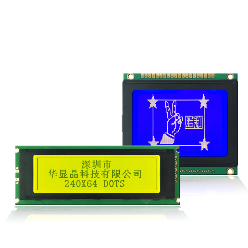
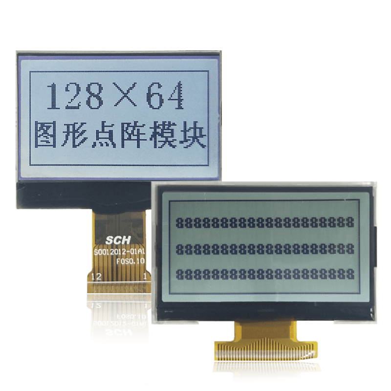
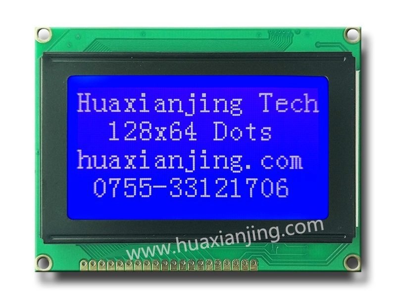
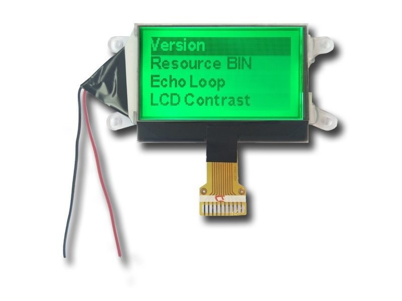
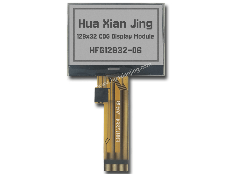
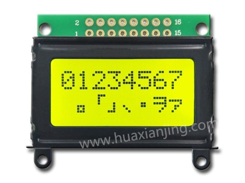
COG (Chip on Glass) and COB (Chip on Board) are two types of LCD technologies. The difference comes from where the control chip, or driver IC, is placed in the display structure.
In a COG display, the IC is mounted directly on the glass. This design removes the need for a separate circuit board, so it makes the display thinner and better for small devices. It also uses fewer wires, which can help reduce failure in the long term.
In a COB display, the IC is mounted on a PCB. This setup takes more space, but it is easier to build and fix. It fits better in devices where size is not a big issue, like factory equipment or home appliances.
How Are COG and COB LCDs Technically Constructed?
COG (Chip on Glass) LCDs and COB (Chip on Board) LCDs differ in how they integrate the driver IC into the display. COG LCDs directly bond the IC to the glass using ACF (Anisotropic Conductive Film). This eliminates the need for a PCB, making the display thinner, lighter, and more compact. On the other hand, COB LCDs place the IC on a PCB, which then connects to the glass. This adds bulk but simplifies assembly.
In actual design projects, the choice between these structures depends on space constraints, production volume, and cost targets. COG modules are often chosen for portable devices, while COB designs are used in applications where cost-saving in low volume and easier repair are priorities. Engineers often weigh manufacturing precision, failure rates, and signal integrity during the design stage.
Key Differences Between COG and COB LCD Constructions
| Feature | COG LCD | COB LCD |
|---|---|---|
| IC Location | On glass | On PCB |
| Bonding Method | ACF (Anisotropic Conductive Film) | Wire bonding or conductive adhesive |
| PCB Presence | None | Present |
| Profile | Thinner | Thicker |
| Connection to Glass | Direct | Via pins or conductive rubber |
| Common Use | Compact devices | General-purpose and industrial displays |
How Do COG and COB Bonding Methods Compare?
ACF bonding (COG) uses Anisotropic Conductive Film (ACF) for a precise, reliable connection between driver IC and glass substrate. Wire bonding (COB, uses adhesive for COB) or adhesive for COB) is less precise but easier to implement. COG offers higher reliability for compact designs, while COB suits simpler manufacturing.
In a COG project, ACF bonding provided a stable connection for a high-resolution display, but the specialized equipment raised costs. In a COB project, wire bonding was faster to set up, but required regular checks for connection issues issues. COG needs advanced equipment for precision, while COB uses common PCB tools, reducing complexity.
| Aspect | ACF Bonding (COG) | Wire Bonding (COB) |
|---|---|---|
| Precision | High, needs alignment | Moderate, less strict |
| Reliability | Strong ACF bond | Good, wire risks |
| Equipment | Advanced, costly | Standard, affordable |
| Complexity | Higher, specialized | Lower, PCB-based |
What Are the Advantages and Disadvantages of COG and COB LCDs?
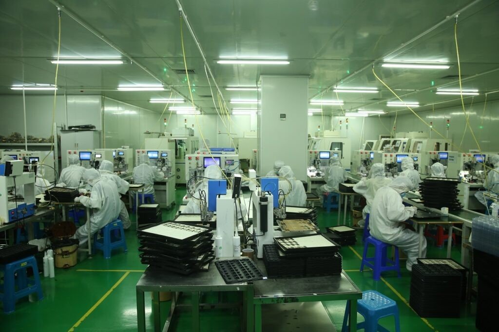
COG (Chip on Glass) LCDs offer a lightweight, slim, and integrated design, which suits modern portable devices. In contrast, COB (Chip on Board) LCDs favor simplicity, repairability, and low initial cost, especially for small production runs. Each approach has specific benefits and trade-offs in design, production, and maintenance.
Design teams often face key decisions when balancing cost, volume, and device constraints. For high-volume compact devices, COG is often preferred. For flexible development cycles or rugged industrial setups, COB provides more accessibility and repair options.
Summary of COG and COB Advantages and Disadvantages
| Feature | COG LCD | COB LCD |
|---|---|---|
| Design | Compact, lightweight | Bulky, includes PCB |
| Production Volume | Cost-effective for high volume | Cost-effective for low volume |
| Reliability | Fewer connections, more stable | Multiple connections, less stable |
| Repairability | Difficult | Easier |
| Setup Cost | Higher (due to ACF) | Lower |
| Application Fit | Portable gadgets | Industrial displays |
Where Are COG and COB LCD Modules Most Commonly Used?
COG LCDs are widely used in compact, portable electronics and automotive interfaces(How Are The LCDs Revolutionizing Automotive Instrument Panel Clusters?). These modules help reduce the product’s thickness and improve reliability due to their simplified structure. COB LCDs, on the other hand, are common in industrial control systems and consumer appliances, where ease of repair and lower development costs matter more than thinness. The selection between COG and COB technologies depends on the project’s priorities, such as device size, production volume, cost limits, and operational durability.
In general, COG LCD modules are ideal for applications that require space-saving and higher connection reliability, while COB modules suit situations where larger size, serviceability, and low setup cost are acceptable. Choosing the right type helps avoid performance issues or cost overruns in the long run(Common Applications for COG LCD Display Modules).
Below is a comparison table summarizing application suitability based on different needs:
| Requirement | Preferred LCD Type | Reason |
|---|---|---|
| Slim device design | COG | No PCB, thin profile |
| High production volume | COG | Cost-effective for mass manufacturing |
| Easy maintenance | COB | IC mounted on PCB, easier to replace |
| Lower initial cost | COB | Simpler bonding, less specialized equipment needed |
| High vibration/shock | COG | Fewer connections, better reliability |
| Display above 4 inches | COB | Better scalability with larger glass-PCB support |
What Makes COG LCD Modules Ideal for Portable and Automotive Uses?
COG displays are preferred in compact electronics like smartphones, smartwatches, and tablets. They’re also widely used in in-car systems, such as dashboards and heads-up displays.
Because the driver IC is bonded directly onto the glass substrate, there’s no need for a PCB, which results in a thinner and lighter design. This structure also means fewer points of failure, which is beneficial for devices exposed to frequent movement, such as wearables or automotive screens. In a production setting, COG’s reduced part count can simplify assembly lines.
Why Are COB LCD Modules Common in Industrial and Household Devices?
COB displays fit well into industrial machines and consumer home appliances like microwaves, coffee makers, or washing machines.
These environments often require basic display functions, lower screen resolution, and most importantly, easy maintenance. Since the IC is bonded onto a separate PCB, it’s simpler to repair or swap out components. The design also allows for more rugged pin connectors, suitable for electrical cabinets or factory panels.
Example use in control panels:
| Application | Reason for Using COB |
|---|---|
| Factory machine interface | Easier to repair with field service technicians |
| Washing machine display | Low cost and long lifecycle expected |
| Ticket vending machine | Larger displays, moderate resolution |
How Does COG and COB Compare with Other LCD Technologies?
COG and COB LCD modules are two of the most used technologies in display integration. However, understanding how they compare to COF (Chip on Film) and SMD (Surface Mount Device) methods helps product designers select the right approach. The key differences lie in assembly methods, space requirements, and flexibility for custom design.
In several projects with compact display integration, COF offered the best results for full-screen borders, while COB remained easier to repair and mount. The right choice depends on product goals, display size, and cost sensitivity.
Here is a detailed comparison by characteristics:
| Technology | IC Placement | Space Profile | Flexibility | Ease of Repair | Cost for Mass Production |
|---|---|---|---|---|---|
| COG | On Glass | Ultra-thin | Moderate | Low | High Efficiency |
| COB | On PCB | Bulkier | Low | High | Costly at scale |
| COF | On Flexible Film | Thin & bendable | High | Low | Moderate |
| SMD | On PCB (soldered) | Moderate | Moderate | Moderate | Moderate |
What Is COF (Chip on Film) and How Does It Compare?
COF (Chip on Film) is a display packaging method where the driver IC is mounted directly on a flexible film instead of glass or PCB. This method supports narrow bezel designs, making it ideal for full-screen smartphones and tablet screens.
Compared to COG, COF is more flexible and bendable, but slightly less compact. Unlike COB, COF is harder to replace but offers a better fit in edge-to-edge designs.
| Feature | COF | COG | COB |
|---|---|---|---|
| Material Base | Flexible Film | Glass | PCB |
| Edge Design Capability | Best for narrow bezels | Moderate | Not suitable |
| Mounting Area | Foldable | Fixed | Fixed |
What Are LCD Modules and How Are They Customized?
LCD modules are pre-assembled units that combine an LCD panel with a driver IC, backlight, interface circuit, and sometimes touch panel. These modules use COG, COB, or COF, depending on project specs.
Manufacturers offer options to adjust backlight type, display resolution, viewing angle, and connector design. A recent OEM wearable project demanded 1.2-inch IPS panel, ultra-thin casing, and SPI interface. COG structure and custom backlight thickness made it feasible.
| Customization Option | Description |
|---|---|
| Backlight | Brightness, color temperature, thickness options |
| Interface | SPI, I2C, MCU parallel |
| Touch Panel | Capacitive or resistive |
| Operating Temperature | Wide or narrow range support |
| Housing | With or without metal frame |
What Are the Types and Variants of COG and COB LCD Displays?
COG and COB LCDs come in different formats, resolutions, and technologies, each optimized for specific applications. COG displays are often used in designs that require graphic interfaces or compact symbol output, whereas COB displays are used where text, symbols, and simple graphics need to be rendered clearly in fixed space environments. The available variants are shaped by the display’s function, pixel density, and backlight or driver support.
By choosing between graphic, character, or segment configurations and considering the use of STN or FSTN film, engineers can match display modules with technical requirements like contrast level, update speed, and power draw. Each display type has a direct influence on the usability and performance of the end device.
Types and Characteristics of COG and COB LCDs
| Display Type | COG LCD | COB LCD |
|---|---|---|
| Graphics Support | Yes, up to 128×64 or higher | Yes, with larger PCBs |
| Segment Display Option | Yes, often compact symbol displays | Yes, widely used in control panels |
| Character Layouts | Limited | 1×8 to 4×40 characters supported |
| Display Film | STN, FSTN available | STN mostly |
| Pixel Density | High, suitable for icons/graphics | Lower, suited for fixed text |
| Application Focus | Compact UIs, custom GUIs | Meters, consoles, appliances |
What Types of Displays Are Available in COG Modules?
COG LCDs are produced in two primary formats: graphic displays and segment displays. Graphic modules, such as 128×64-pixel screens, support icons, charts, and detailed layouts, and are common in compact devices like handheld testers, wearables, and control systems.
Segment-based COG modules are used where only predefined characters or shapes are needed, such as calculators or simple remote controls. These displays benefit from COG’s slim structure and high contrast when paired with STN or FSTN layers, which improve clarity and readability under various lighting conditions.
What Are the Common Display Variants in COB Modules?
COB displays are often configured as character LCDs with standard formats such as 8×1, 16×2, or 40×4 characters. These are used in status displays, industrial readouts, and basic HMI interfaces.
COB can also support graphic or segment displays, particularly in cases where durability, component separation, or easy repair is required. Due to the space provided by the PCB, additional circuits such as voltage boost or input buffering can be included in the same module.
Typical COB Display Configurations
| Type | Character Format | Usage Example |
|---|---|---|
| Character Display | 8×2,16×2, 20×4 | Industrial meters, control panels |
| Graphic Display | 128×64, 240×128 | Vending machines, lab instruments |
| Segment Display | Custom symbol sets | Appliances, thermostats |
How to Decide Between COG and COB LCD Modules?
| Consideration | COG Module | COB Module |
|---|---|---|
| Size Limitations | Best for small/thin devices | Accepts more space |
| Budget Flexibility | Higher setup cost, lower per-unit at volume | Lower setup cost, higher unit at scale |
| Production Volume | High-volume efficient | Ideal for low volume |
| Repair Requirements | Not repair-friendly | Easily serviceable |
| Design Changes | Fixed IC, less flexible | Modular layout, adaptable |
| Example Application | Smartwatch, stylus, compact scanner | Factory panel, ticket kiosk, thermostat |
What Are the Key Criteria When Choosing Between COG and COB?
When evaluating COG or COB, product teams should consider:
- Display Size: Can the device afford a thicker profile (COB), or must it stay ultra-slim (COG)?
- Budget: Is the priority lower per-unit cost at scale (COG) or low upfront cost (COB)?
- Reliability Needs: Is the product exposed to vibration or sealed environments?
- Repair Strategy: Will technicians need to swap parts?
- Production Scale: Are you building 10 or 10,000 units?
Scenario Example:
- A fitness tracker benefits from COG due to its size and production volume.
- An industrial oven control panel favors COB due to larger display tolerance and easier repair.
How Can You Effectively Integrate COG or COB Modules into Projects?
| Symptom | Cause | Fix |
|---|---|---|
| Flickering | Weak voltage regulation | Add decoupling capacitor |
| Low contrast | Incorrect bias voltage | Adjust V0/VEE input |
| No display | Wrong data sequence | Recheck SPI/I2C init routine |
| Signal noise | Long or floating wires | Shorten or pull-down unused lines |
How to Simplify COG/COB Technical Concepts for Non-Experts?
Many users confuse the acronyms COG, COB, and COF. Here’s a quick explanation:
- COG: Chip on Glass – the driver IC is bonded directly to the display glass.
- COB: Chip on Board – the driver IC is mounted on a PCB connected to the display.
- COF: Chip on Film – the IC is on a flexible film, often for borderless screens.
Related Articles:
Why Do High-Lumen Lights Fail in Outdoor Environments?
How Do Sunlight-Readable LCDs Maintain Contrast Outdoors?
How Do Manufacturers Ensure Color Accuracy in Production?
How is CAN or LIN Bus Integration Handled with LCD Modules?
How Do Rise and Fall Times of the Enable Pin Affect Data and Display Quality in LCD1602 Modules?
FAQ
Can COG or COB displays work in extreme temperatures?
COG displays handle extreme temperatures well due to their compact design. COB displays may need extra protection for PCB connections.
What is the difference between COG and COF in display manufacturing?
COG bonds the driver IC directly to the glass for a compact design. COF uses a flexible film, allowing for thinner borders in modern smartphones
How do I choose the right backlight for COG or COB displays?
Select a backlight based on visibility and power consumption. COG often uses LED backlights for compact devices, while COB suits larger, adjustable options.
Are COG and COB displays compatible with touchscreens?
Both COG and COB displays can integrate with touchscreens. COG needs precise alignment, while COB simplifies touchscreen connections via PCB.
What is the typical lifespan of COG and COB displays?
COG displays last longer in stable conditions due to fewer connections. COB displays may need maintenance but are durable for industrial use.


