A level shifter safely connects a 3.3V LCD module to a 5V system by translating signal voltages to a range the display can handle. Power the high-voltage side of the shifter with 5V and the low-voltage side with 3.3V, and connect all grounds together. Use a bidirectional level shifter for I2C LCD modules, or a unidirectional shifter for parallel interfaces, making sure to match the channel count to the number of LCD lines. Always check logic level compatibility and wiring to prevent display errors or damage.
Why Are Level Shifters Required When Using 3.3V LCD Modules?
Level shifters are required for 3.3V LCD modules because the logic levels from a 5V system are not safe for a 3.3V device. If a 5V logic signal connects directly to a 3.3V LCD input, the input can receive too high a voltage. This may cause overvoltage damage to the LCD. Most 3.3V LCDs use CMOS technology, where even short exposure to high voltage can break the input circuit or lead to errors. Level shifters make the voltage safe, matching the signal to what the LCD can accept. This is the only way to achieve signal voltage compatibility and reliable input protection.
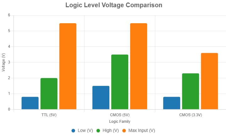
When engineers work with different digital logic types, the most common are TTL logic levels and CMOS logic levels. TTL logic levels use 0.8V as the “low” value and 2V as “high,” but the real output can be as high as 5V. CMOS logic levels change with supply voltage. In a 3.3V system, “high” means above 2.3V, and the input must not exceed 3.6V(Detailed Explanation of TTL Signal and LVDS Signal in LCD). A 5V logic output is much too high for a 3.3V LCD. Using a level shifter makes the signal safe, prevents overvoltage damage, and avoids complex failures. In multi-power systems, without level shifters, there is a risk of CMOS latch-up—a dangerous state that can burn out input pins.
| Logic Family | Low (V) | High (V) | Max Input (V) | 3.3V LCD Safe? |
|---|---|---|---|---|
| TTL (5V) | <0.8 | >2.0 | 5.5 | No |
| CMOS (5V) | <1.5 | >3.5 | 5.5 | No |
| CMOS (3.3V) | <0.8 | >2.3 | 3.6 | Yes |
| 3.3V LCD Input | <0.8 | >2.3 | 3.6 | Yes |
Understanding Logic Levels: What Makes TTL and CMOS Different?
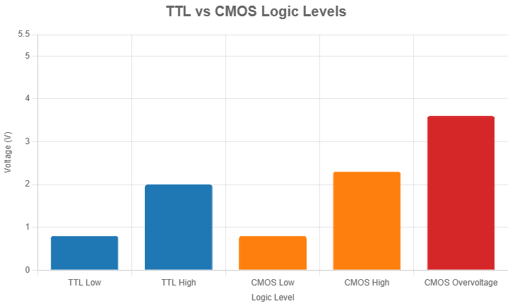
TTL logic levels use 0.8V for “low” and 2V for “high.” The output swings from 0V up to 5V, which is too much for a 3.3V LCD input. CMOS logic levels in 3.3V systems define “high” as above 2.3V, but input voltage must always stay under 3.6V. This means the signal from a 5V device is always too high for safe operation.
Field experience shows direct connection from 5V output to 3.3V LCD input is a common cause of display faults. 3.3V LCD modules may work for a short time, but overvoltage eventually damages the display or causes strange behavior. CMOS latch-up happens more often in multi-power systems when supply rails power up in different order. The LCD may heat up or shut down.
Engineers always check logic level standards before connecting boards. Inconsistent logic levels are the main cause of input protection failures, especially in prototyping or when mixing new LCD modules with old microcontrollers.
| Logic Family | Low (V) | High (V) | Max Input (V) |
|---|---|---|---|
| TTL (5V) | <0.8 | >2.0 | 5.5 |
| CMOS (5V) | <1.5 | >3.5 | 5.5 |
| CMOS (3.3V) | <0.8 | >2.3 | 3.6 |
Risks of Direct Connections: What Problems Happen Without Level Shifters?
Applying a 5V logic signal directly to a 3.3V LCD input stresses the internal transistor of the input. Overvoltage breaks down the protection diode, which can cause failure either immediately or after repeated use. LCD modules may show lines, flicker, or stop working.
In systems with both 3.3V and 5V rails, especially where users connect and disconnect power, CMOS latch-up is common. The input circuit latches in a state where it shorts VCC to GND, causing heat, noise, or permanent damage. These failures are often found after field deployment(Why Do Some LCD Modules Require a Negative Voltage for Contrast Adjustment?).
Using a level shifter keeps signals within safe limits, prevents silent failures, and lets designers follow datasheet rules. Most LCD module makers reject warranty claims if the input voltage exceeds maximum ratings, making level shifting a must for safe operation.
Connecting a Level Shifter for 3.3V LCD Modules
To properly connect a level shifter for a 3.3V LCD, the high-voltage (HV) side should be powered with 5V, and the low-voltage (LV) side with 3.3V. All grounds from the microcontroller, LCD module, and level shifter must be connected to a common ground. Signals from the 5V system should be routed into the HV side of the level shifter, and the shifted 3.3V signals should exit the LV side into the LCD input pins(How Do You Choose the Best Microcontroller or Processor for Your LCD Module Project?).
Incorrect wiring can cause data corruption or damage to the LCD. For example, if the grounds aren’t common, voltage levels become undefined. If the level shifter is not powered correctly, signals may not shift at all. When using serial protocols like I2C or parallel buses, selecting the correct type of level shifter is critical for stable operation.
Basic Wiring Setup
To connect a level shifter for a 3.3V LCD module, follow these steps:
- Power the level shifter: Connect the high-voltage (HV) side to 5V and the low-voltage (LV) side to 3.3V. These can come from your microcontroller or an external power supply.
- Establish a common ground: Link the grounds of the microcontroller, LCD, and level shifter together. This ensures stable communication and prevents issues like random display outputs.
- Route the signals: Send 5V signals (e.g., SDA and SCL for I2C, or data/control lines for parallel setups) from the microcontroller to the HV pins of the level shifter. Then, connect the LV outputs to the LCD’s input pins. This steps down the voltage to a safe 3.3V for the LCD(What Are the Differences Between SPI and I2C for LCD Modules?).
A proper ground connection is critical—without it, the LCD might not respond or could display garbage data. Here’s a simple diagram:

I2C Interface for LCDs
For LCDs with an I2C interface (like a 16×2 LCD with an I2C backpack), the level shifter setup requires attention to the bidirectional nature of I2C communication:
- Power the shifter: HV side to 5V, LV side to 3.3V.
- Connect signal lines: Route the SDA (data) and SCL (clock) lines from the microcontroller to the HV pins. Use a bidirectional level shifter for SDA (since data flows both ways) and a unidirectional shifter for SCL (a one-way clock signal). Connect the LV outputs to the LCD’s SDA and SCL pins.
- Add pull-up resistors: Place 10kΩ pull-up resistors on both the HV and LV sides of the SDA and SCL lines to ensure reliable I2C communication.
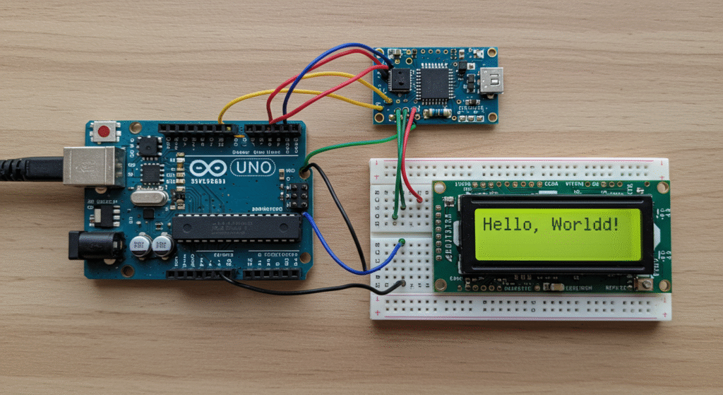
For example, when wiring a 16×2 LCD with an I2C backpack, missing pull-up resistors can lead to unstable communication. Adding them resolves this. Here’s a basic Arduino code snippet to initialize it, check the LCD’s datasheet for the exact I2C address (e.g., 0x27 might vary):
					#include <LiquidCrystal_I2C.h>

LiquidCrystal_I2C lcd(0x27, 16, 2);  // Set LCD address to 0x27 for a 16x2 display

void setup() {
  lcd.init();  // Initialize the LCD
  lcd.backlight();  // Turn on the backlight
  lcd.setCursor(0, 0);
  lcd.print("Hello, World!");
}

void loop() {
  // Add your code here
}
Parallel Interface for LCDs

For parallel interfaces (e.g., 4-bit or 8-bit mode on a 16×2 LCD), parallel setups require more wiring than I2C but offer direct control over the LCD(How Can a Serial In and Parallel Out Shift Register Simplify MCU to LCD Communication?). unidirectional level shifters are used for all lines:
- Power the shifter: HV side to 5V, LV side to 3.3V.
- Connect the lines: Route the data lines (D0-D7 for 8-bit, D4-D7 for 4-bit) and control lines (RS, RW, EN) from the microcontroller to the HV pins. Connect the LV outputs to the matching LCD pins.
- Ground everything: Ensure a common ground across all components.
For a 4-bit setup, you’d need shifters for D4-D7, RS, RW, and EN (7 lines total). In 8-bit mode, add D0-D3 (11 lines total). Here’s a pin connection table for 4-bit mode:
| Microcontroller Pin | Level Shifter HV | Level Shifter LV | LCD Pin |
|---|---|---|---|
| D4 | HV1 | LV1 | D4 |
| D5 | HV2 | LV2 | D5 |
| D6 | HV3 | LV3 | D6 |
| D7 | HV4 | LV4 | D7 |
| RS | HV5 | LV5 | RS |
| RW | HV6 | LV6 | RW |
| EN | HV7 | LV7 | EN |
Designing Custom Level Shifter Circuits
MOSFET-Based Bidirectional Shifter
Schematic:
This design uses an N-channel MOSFET (e.g., 2N7000 with a low Vgs threshold) and two 10kΩ pull-up resistors—one connected to the high-voltage (HV) side (e.g., 5V) and one to the low-voltage (LV) side (e.g., 3.3V). The MOSFET’s drain connects to the HV side, the source to the LV side, and the gate to ground.
Operation:
- Low-to-High Translation: When the LV side goes low (0V), the MOSFET turns on, pulling the HV side low. When the LV side is high (3.3V), the MOSFET turns off, and the HV pull-up resistor pulls the HV side to 5V.
- High-to-Low Translation: When the HV side goes low (0V), the MOSFET conducts, pulling the LV side low. When the HV side is high (5V), the MOSFET turns off, and the LV pull-up resistor pulls the LV side to 3.3V.
Suitability:
Ideal for bidirectional, low-speed interfaces like I2C, where signals must flow in both directions between devices operating at different voltages (e.g., a 5V microcontroller and a 3.3V sensor).
Transistor-Based Unidirectional Shifter
Schematic:
This design employs an NPN transistor (e.g., BC547) with a 2.2kΩ base resistor connected to the input (LV side) and a 10kΩ pull-up resistor from the collector to the HV supply (e.g., 5V). The emitter is grounded.
Operation:
- When the LV input is high (3.3V), the transistor turns on, pulling the collector (HV output) low (0V).
- When the LV input is low (0V), the transistor turns off, and the pull-up resistor pulls the collector to 5V.
- Logic Inversion: The output is inverted relative to the input, so software compensation (e.g., inverting the signal logic) may be required.
Suitability:
Simple and effective for unidirectional signals, such as parallel LCD data lines, where a 3.3V microcontroller needs to drive a 5V display.
					void setup() {
  pinMode(dataPin, OUTPUT);
}

void loop() {
  digitalWrite(dataPin, !desiredState);  // Invert the logic for transistor shifter
}
Voltage Divider for 5V-to-3.3V Shifting
Schematic:
Use two resistors in series: R1 = 10kΩ connected to the 5V input and R2 = 22kΩ connected to ground. The output (3.3V) is taken from the junction of R1 and R2.
Operation:
The voltage divider reduces the input voltage based on the resistor ratio:
Limitations:
- High-Speed Unsuitability: The resistors and parasitic capacitance create RC delays, making it impractical for fast signals.
- Unidirectional: It only steps down voltage (e.g., 5V to 3.3V) and cannot translate signals in the opposite direction.
Suitability:
Best for low-speed, unidirectional signals, such as a control line in a simple interface.
Component Selection
To ensure reliable operation, choose components carefully:
- MOSFETs: Select N-channel MOSFETs with low Vgs thresholds (e.g., <1.5V), such as the 2N7000 or BS170, for proper switching with 3.3V signals. Check datasheets to confirm compatibility.
- Transistors: Use common NPN transistors like BC547 or 2N3904 for unidirectional shifters.
- Resistors:
- MOSFET Shifters: 10kΩ pull-ups balance current draw and signal speed.
- Transistor Shifters: Pair a 2.2kΩ base resistor with a 10kΩ pull-up for efficient operation.
- Voltage Dividers: Use values like 10kΩ and 22kΩ for 5V-to-3.3V shifting, ensuring minimal current draw.
How Should You Select Commercial Level Shifters for LCD Modules?
To select a commercial level shifter for an LCD module, you need to match the signal direction, channel count, and speed with your application. Use bidirectional ICs for protocols like I2C, and unidirectional ICs for data/control lines in parallel LCDs. Choose ICs with the correct number of channels and verify the noise margin and switching speed support your communication frequency(What Are the Differences Between SPI and I2C for LCD Modules?).
Using the wrong IC type may cause data loss, glitches, or LCD malfunction due to timing mismatches or insufficient drive capability.
What Are the Types of Level Shifter ICs?
Level shifter ICs come in single-channel, dual-channel, 4-channel, or 8-channel packages. These are available as either unidirectional or bidirectional devices.
- Bidirectional ICs are used for I2C, where signals flow both ways.
- Unidirectional ICs are suited for parallel LCDs, where the microcontroller drives the LCD.
Multi-channel ICs save board space and simplify routing. For example, an 8-channel unidirectional IC can shift all D0–D7 signals on a parallel LCD.
Table of IC Types:
| IC Type | Direction | Channel Count | Best Use Case |
|---|---|---|---|
| Single Channel | Uni/Bi | 1 | Simple GPIO or SPI |
| 2-Channel | Bidirectional | 2 | I2C (SDA + SCL) |
| 4-Channel | Uni/Bi | 4 | SPI or 4-bit LCD |
| 8-Channel | Unidirectional | 8 | 8-bit parallel LCD |
What Features Matter When Choosing a Level Shifter?
Channel count must match the LCD interface type:
- I2C LCDs need 2 channels (SDA + SCL)
- 4-bit parallel LCDs require 6 channels (4 data + RS + EN)
- 8-bit parallel LCDs may need 11 channels (D0–D7 + RS + RW + EN)
Speed rating must support your protocol:
- I2C requires up to 400kHz
- Parallel interfaces may exceed 1 MHz
Noise margin must allow signals to be read cleanly. Ensure VIH(min) and VIL(max) align with your MCU and LCD voltage levels.
Table of Feature Requirements:
| Feature | Minimum Requirement | Why It Matters |
|---|---|---|
| Channels | Match LCD pin count | Prevent unused or missing signals |
| Speed | >1 MHz for parallel, 400kHz I2C | Avoid timing issues in fast interfaces |
| VIH/VIL margins | Compatible with logic levels | Ensures reliable logic recognition |
FAQ
Do I need level shifting for SPI communication with a 3.3V LCD?
Yes, especially for signals like MISO and MOSI if voltages differ. Bidirectional shifting is often needed.
Can You Use a Level Shifter for Other 3.3V Devices Besides LCDs?
Yes, level shifters work for any 3.3V device, like sensors or modules, needing 5V signal translation. Ensure the shifter matches the signal count and speed of the device.
What Happens If You Skip Using a Level Shifter?
Skipping a level shifter risks overvoltage damage to the 3.3V LCD, causing malfunctions or permanent failure. Always use a shifter for 5V-to-3.3V communication.
Are Level Shifters Necessary for All 5V Microcontrollers?
Some 5V microcontrollers have 3.3V-compatible outputs, but most require level shifters for 3.3V LCDs. Check the microcontroller’s data sheet to confirm.
How Do You Minimize Power Consumption in Level Shifter Circuits?
Choose low-power level shifters and optimize resistor values to reduce current draw. For example, use higher-value pull-up resistors like 10kΩ for I2C.