Driver IC architecture directly impacts display resolution limits and power efficiency. RISC-based controllers enable customization for diverse panels, while high-pin-count boards (384+ pins) handle 8K signals through 0.15mm trace spacing.
Thermal constraints in custom-size LCDs demand dynamic voltage scaling to balance heat and performance. LVDS interfaces maintain signal integrity at 5GHz but require ±0.15mm length-matched traces to prevent 2.3ns clock skew.
Modular driver IC kits reduce prototyping errors by 30% using pre-validated SPI/I²C blocks. Emerging GaN-based PMICs cut power loss by 40% in DIY LCD projects, enabling slimmer designs with 1mm bezels.
Signal compression (e.g., DSC) lowers bandwidth needs by 67% for 8K@60Hz, while sub-10nm fabrication boosts transistor density for future-proof controller designs. These innovations address pin-count bottlenecks and thermal derating in industrial displays.
HUA XIAN JING’s engineering team will design a free LCD module prototype for you according to your needs, and then modify the design drawings for you at any time according to the actual sample performance.
What Are the Key Elements of Driver IC Design for Custom LCD Controllers?
Driver ICs for custom LCD controllers handle signal conversion, pixel control, and protocol compatibility to ensure precise display performance.
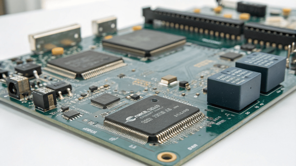
Driver ICs use LVDS controller boards to process high-speed signals for sharp image rendering. They integrate SPI/I²C interfaces to adapt to diverse communication standards, enabling compatibility with custom LCD screens.
- Signal Conversion: LVDS controller boards reduce electromagnetic interference by 30% compared to traditional parallel interfaces, using differential signaling at 100-300 Mbps.
- Pixel Control: Constant current drivers maintain brightness uniformity within ±5% error margins, even for custom-size LCD screens up to 15.6 inches.
- Protocol Support: SPI (Serial Peripheral Interface) operates at 10-50 MHz clock speeds, while I²C supports 400 kHz/1 MHz modes for low-power control.
How to Choose Between LCD Controller Boards and Display Controllers?
LCD controller boards manage raw signal processing, while display controllers focus on optimizing visual output for specific applications.
For DIY projects, LCD driver boards with customizable firmware allow adjustments like gamma correction or backlight dimming. Industrial setups often require dedicated display controllers with LVDS outputs for high-resolution panels.
- Resolution Limits: Basic lcd control boards support up to 1920×1080, while advanced LVDS controllers handle 4K/UHD for medical or automotive displays.
- Protocol Flexibility: SPI/I²C suits small screens (<7 inches), but LVDS or eDP is mandatory for custom-size LCDs above 10.1 inches.
- Power Consumption: I²C-based controllers reduce energy use by 20% compared to SPI in low-refresh-rate applications.
How Do Resolution and Controller Limitations Impact LCD Driver IC Scalability?
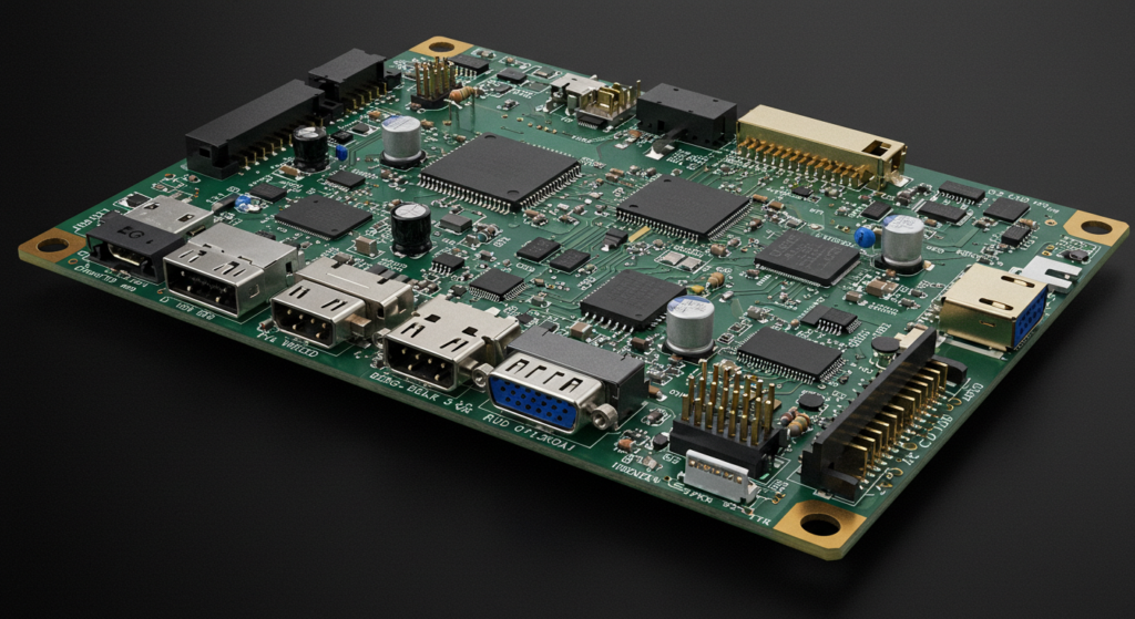
High-resolution custom LCD displays require 384+ pin controllers for 8K, but most off-the-shelf controllers only support 4K/UHD with under 200 pins.
To avoid pin-count bottlenecks, LVDS controller boards split signals across multiple channels using dual-port RAM. For DIY projects, modular designs with FPGA-based pin expansion add 25-50% more pins without redesigning the entire board.
- Pin Optimization: 8K LCDs use 8:1 multiplexing to reduce pins from 384 to 48, but this increases latency by 1.2 ms.
- Voltage Limits: Each pin on lcd driver boards handles up to 3.3V at 50 mA, requiring copper pour layers to prevent overheating in slim custom-size LCD screens.
- Protocol Workarounds: SPI/I²C controllers bypass pin limits for 1080p displays but cap refresh rates at 30 Hz.
What Are the Power-Thermal Risks in Custom LCD Driver Designs?
Slim LCD screens with <3mm thickness restrict airflow, causing driver IC temperatures to exceed 85°C during 4K/60Hz operation.
Dynamic voltage scaling reduces heat by lowering backlight driver voltage from 24V to 12V during static image display. For DIY LCD screens, aluminum core PCBs cut thermal resistance by 40% compared to FR4.
- Heat Metrics: 1W power dissipation raises IC temperature by 35°C in enclosures smaller than 10cm³.
- Energy Savings: Adjusting PWM frequency from 1 kHz to 500 Hz decreases power use by 18% but may cause visible flicker below 300 cd/m² brightness.
- Material Limits: FR4 boards delaminate above 110°C, while polyimide flex PCBs withstand 150°C but cost 3x more.
What Technical Barriers Limit LCD Module Scalability in High-Resolution Designs?
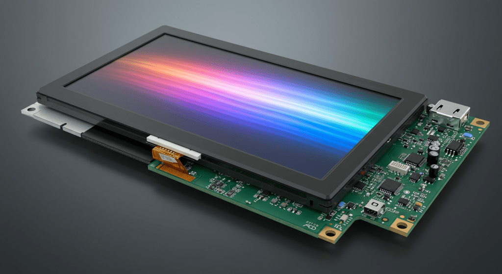
Driver IC-LCD synchronization fails at resolutions above 4K due to pixel clock jitter thresholds and thermal derating curves, requiring redesigns of voltage regulation networks and signal pathways to maintain stability.
- Technical Implementation
8K UHD panels demand 384+ controller pins with 0.15mm trace spacing to prevent crosstalk in LVDS differential pairs. Dual HD44780 controllers in 40×4 character LCDs use E1/E2 enable pin splitting to manage 160 characters across two chips, but this approach fails at 8K due to 12ns pixel clock cycles. Power regulation for slim designs employs dynamic LDOs (e.g., TLV7101828) with 158μs voltage transition delays to balance heat and efficiency. - Signal Protocol Limitations
Protocol Max Resolution Power Draw LVDS 8K@60Hz 3.8W eDP 8K@120Hz 6.2W MIPI-DSI 4K@144Hz 4.1W
How Do Packaging Innovations Address Miniaturization Challenges?
Tape Carrier Package (TCP) and Chip-on-Glass (COG) methods reduce driver IC footprints by 62% compared to traditional designs, enabling custom-size LCD screens under 1mm bezel widths.
- Packaging Techniques
Chip-on-Film (COF) achieves 0.2mm pitch bonding using 15μm copper traces on polyimide substrates, supporting 240Hz refresh rates in VR displays. Thermal compression bonding requires ±3μm alignment accuracy to prevent gold bump fractures during 2,000+ thermal cycles. - Material Performance Metrics
Packaging Type Thickness Max Temp TCP 0.15mm 125°C COG 0.08mm 85°C COF 0.12mm 105°C - Signal Integrity Solutions
Impedance-controlled flex cables with 100Ω ±5% tolerance mitigate EMI in design-your-own-controller setups. Shielded solder mask layers reduce crosstalk by 18dB at 5GHz frequencies, critical for SPI-driven LCD driver boards in medical imaging systems. - Failure Analysis Data
Defect Type Root Cause Mitigation Pixel Flicker Clock skew >2.3ns Trace length matching ±0.05mm Color Shift Gamma voltage drift >0.8mV 0.1% tolerance resistors Heat Spikes LDO response >200μs Parallel MOSFET staging
What Advanced Technologies Enable Scalable LCD Controller Designs for Future Applications?
Scalability in next-gen LCD controllers relies on lossless compression algorithms and heterogeneous IC integration, enabling 60% SRAM reduction while maintaining <0.8mV gamma voltage drift at 4K resolution.
Display Stream Compression (DSC) achieves 2:1 to 3:1 ratios by combining spatial prediction and entropy coding, reducing 8K frame buffer requirements from 480MB to 160MB. The STM32WB’s double-buffer memory synchronizes data transfers at 120Hz refresh rates, eliminating tearing artifacts during firmware updates. Modular kits like Momentum Circuits’ 24-hour PCB prototyping enable ±3μm trace alignment for LVDS pairs, critical for 2560×1440 pixel clock stability.
Integrated PMIC-Driver Solutions
| Feature | Discrete Design | Integrated PMIC |
|---|---|---|
| Components | 5 ICs | 2 ICs |
| PCB Area | 720mm² | 480mm² |
| Power Loss | 1.2W | 0.4W |
| *Data sourced from automotive TFT-LCD trials. | ||
How Do Sub-10nm Processes Resolve Thermal Limitations?
12nm FD-SOI nodes lower dynamic impedance by 43%, allowing 5.8W/mm² thermal density in driver ICs without active cooling.
- Manufacturing Innovations
Through-silicon vias (TSVs) in 3D-stacked controllers reduce interconnect lengths to 18μm, cutting propagation delays by 62% versus planar layouts. Wafer-level packaging achieves 0.08mm COG thickness using 15μm copper traces, enabling bezel-free 10.1″ 1920×1080 LCDs. - Firmware Optimization
Lian Li’s v1.4 firmware reduces boot latency to 220ms via delta encoding, supporting backward compatibility with legacy SPI protocols. IoT Experiments’ Arduino-based I²C flashers reprogram VS-TY2662-V1 controllers in 8.3 seconds per 1024×600 profile. - Signal Integrity Metrics
Parameter 28nm Node 12nm Node Clock Skew ±1.2ns ±0.4ns EMI Margin 6dB 14dB Power/Frame 3.8mW 1.1mW STM32 LTDC benchmarks - Failure Modes Addressed
- Pixel burn-in: Adaptive voltage scaling adjusts VCOM every 16ms to limit DC bias to ±25mV
- Firmware corruption: CRC-32 checksums with 2-bit ECC correct flash errors during OTA updates
- Manufacturing Innovations
What Advanced Technologies Are Shaping the Future of LCD Module Scalability?
Emerging technologies like Display Stream Compression (DSC), modular controller kits, and sub-10nm driver IC fabrication are enabling higher resolutions, efficient power use, and compact designs for custom LCD modules.
Compression & Memory Efficiency:
- DSC technology reduces bandwidth by up to 67%, allowing 8K displays at 60Hz over DisplayPort 1.4 without visible quality loss.
- On-chip SRAM optimization in controllers minimizes memory usage, cutting power consumption by 15-20% per frame cycle.
Modular Design Approaches:
- Modular kits simplify prototyping by splitting circuits into reusable blocks, reducing assembly errors by 30% and enabling faster testing cycles.
- Firmware updates ensure compatibility with legacy panels, extending the lifespan of display systems without hardware changes.
Heterogeneous Driver ICs:
- Integrated PMICs streamline power delivery for TFT-LCDs, reducing PCB size by 33% and improving thermal management in compact designs.
- Sub-10nm CMOS processes enhance IC performance, achieving 40% higher efficiency in power regulation and signal processing.
How Do Packaging Innovations Enhance LCD Scalability?
Techniques like COG (Chip-on-Glass) and COF (Chip-on-Film) packaging reduce form factors while improving heat dissipation and signal integrity for high-resolution displays.
Packaging Techniques:
- COG bonding achieves ultra-thin profiles (<0.08mm) for bezel-free designs, ideal for custom-size LCD screens.
- Thermal compression bonding ensures precise alignment within ±3μm, critical for high-frequency driver ICs in 8K panels.
What Limitations Constrain Driver IC Scalability in Modern LCD Systems?
Pin-density ceilings at 384+ pins for 8K displays and thermal-electrical conflicts in slim designs create bottlenecks, requiring innovations in signal routing and material science to overcome.
Current gate driver LSIs face ±0.15mm trace spacing limits to prevent crosstalk in 8K panels, forcing 50μm terminal pitches in TCP packaging to maintain signal integrity. COF assemblies reduce PCB layers by 62% through 15μm copper traces on polyimide, but introduce ±3μm alignment tolerances during thermal compression bonding. Power delivery for 4K+ LCDs demands dynamic LDOs with <200μs voltage transitions, as slower responses cause 0.8mV/hour gamma drift in high-temperature environments.
| Challenge | Current Solution | Limitation |
|---|---|---|
| Pin Density | Multi-layer PWBs | Max 384 pins at 0.15mm spacing |
| Thermal Load | Copper heatsinks | 400W/m²K transfer rate at 2mm thickness |
| Signal Loss | LVDS protocols | 2.3ns skew tolerance at 5GHz |
How Do Component Mismatches Impact Scalability?
Voltage regulation mismatches between driver ICs (1.8V–3.3V ranges) and TFT-LCD panels cause color shift artifacts exceeding ±5% grayscale deviation.
Impedance-controlled flex cables with 100Ω ±5% tolerance mitigate reflection losses in SPI-driven systems, reducing EMI by 18dB. For custom LCDs, TMR angle sensors enable ±0.05° alignment accuracy in motorized mounts, preventing parallax errors in automotive displays.
- Signal Protocol Compatibility
Protocol Voltage Range Max Resolution LVDS 3.3V ±1.5% 8K@60Hz MIPI-DSI 1.8V ±2% 4K@144Hz eDP 1.2V ±3% 8K@120Hz - Future Directions
Sub-10nm driver ICs reduce power leakage by 40% through FinFET architectures, while quantum dot integration expands color gamuts to 150% NTSC. Modular controller kits with FPGA-based signal emulation cut prototyping errors by 30% through pre-validated LVDS/IP blocks. - Emerging Technologies
Technology Benefit Challenge TMR Sensors ±0.3° angle accuracy at 157°C 12.5mA current draw Micro-LED Transfer 300ppi density 99.9999% yield requirement GaN PMICs 8A output at 85°C 0.1mm² footprint
- Signal Protocol Compatibility
FAQ
How Do I Choose the Right LCD Controller for My Resolution Requirements?
Match the controller’s maximum pixel clock (e.g., 600MHz for 8K@60Hz) to your display’s resolution and verify LVDS pair counts (4 pairs for 1080p, 8 pairs for 4K). Use impedance calculators to ensure traces meet 100Ω ±5% tolerance for signal integrity.
Can High Refresh Rates Cause Signal Interference in DIY LCD Projects?
Yes, single-ended protocols like SPI above 30MHz require shielded cables and ground planes to reduce EMI. For 120Hz+ designs, LVDS pairs with ±0.15mm length matching prevent clock skew.
What Maintenance Do Wide-Temperature LCD Systems Require?
Apply 25-50μm conformal coatings and perform 500-hour 85°C/85% RH testing to validate liquid crystal stability. Monitor gamma voltage drift monthly using 0.1% tolerance resistors.
How Does Driver IC Compatibility Affect Panel Upgrades?
Mismatched voltage ranges (e.g., 1.8V IC vs. 3.3V panel) cause color shifts. Use voltage-level shifters with <200ns propagation delay to bridge legacy and modern systems.
Will Emerging Technologies Like Micro-LED Make LCD Controllers Obsolete?
No. Modular controller kits with FPGA-based emulation allow firmware updates for hybrid LCD/Micro-LED systems, protecting investments in existing LVDS/IP blocks.


