Signal timing controls data transfer in LCD displays. It ensures clear, stable images. HSYNC and VSYNC sync pixel rows and frames. DE enables pixel data transmission. DCLK sets the pixel clock speed. Incorrect timing causes flicker or ghosting. Proper timing from datasheets prevents these artifacts. Engineers adjust sync signals for TN or IPS panels. Timing diagrams help optimize RGB displays. These steps maintain display quality across LCD systems.
How Do Synchronization Signals Ensure Accurate Pixel Data in RGB Displays?
Synchronization signals including HSYNC, VSYNC, DE, and DCLK—play a crucial role in RGB display systems. They coordinate the flow of pixel data, aligning every bit of information to the correct place on the screen. HSYNC signals mark the end of each scan line, preparing the system to start the next row. VSYNC indicates the completion of a frame, resetting the display back to the top-left pixel. DE (Data Enable) specifies periods when pixel data is valid within the active area of the display. DCLK is the pixel clock that keeps all RGB data transmission in sync, providing precise timing for every pixel rendered. With these signals, the display hardware can prevent misalignment, signal overlap, and ensure the stable presentation of every image(How do timing controllers (TCON) synchronize image data in LCDs?).
When working on display projects, engineers rely on these signals to avoid data corruption, eliminate tearing artifacts, and maintain a consistent image. For example, in an embedded LCD project, failing to set the correct HSYNC or VSYNC timing may cause the entire image to shift or flicker. Precise configuration of the DCLK is necessary to match the pixel rate of the LCD panel. In modern TFT LCD modules, DE mode is preferred for its ability to simplify timing by marking only the periods with valid data, reducing timing complexity and improving compatibility with graphic LCD systems.
Below is a signal timing table that illustrates how these synchronization signals interact in an RGB display module:
| Signal | Function | Triggers | Impact |
|---|---|---|---|
| HSYNC | End of scan line | Next row start | Row alignment |
| VSYNC | End of frame | Top row start | Frame alignment |
| DE | Valid pixel data | Active region | Data gating |
| DCLK | Pixel clock | Pixel timing | Synchronization |
What Are HSYNC, VSYNC, DE, and DCLK in RGB Displays?
HSYNC triggers the end of each scan line, starting a new row on the LCD panel. VSYNC signals the end of each frame, sending the system back to the first pixel of the next frame. DE (Data Enable) marks the period where pixel data is actively transmitted to the screen. DCLK (Pixel Clock) provides the basic rhythm, controlling the pace at which each pixel is sent and displayed. These signals must work together to maintain a clear and stable image, preventing display issues like flicker or image tearing. Missing or misaligned signals may cause lines or frames to appear out of order or cause data loss.
In projects using graphic LCD modules, engineers often adjust these signals to fit specific panel requirements. For example, matching the DCLK frequency to the panel’s maximum rate helps maintain image clarity. Careful timing of DE is essential in displays that use high refresh rates or unique resolutions.
- HSYNC: Marks the end of a scan line (row transition)
- VSYNC: Signals the end of a frame (frame transition)
- DE: Specifies periods with valid pixel data
- DCLK: Maintains pixel-level timing
Why Are Synchronization Signals Necessary in RGB Displays?
Synchronization signals are essential for accurate timing between the display controller and the LCD module. They help prevent clock drift, keeping every line and frame in order. Without these signals, pixel data could be mapped incorrectly, leading to unstable or misaligned images. In the process of designing LCD systems, improper synchronization may result in image artifacts, flickering, or total loss of the displayed image(How to Troubleshoot and Test Your Monochrome LCD Module).
During the development of embedded LCD solutions, developers must always ensure that synchronization signals are correctly set according to the timing requirements of each display module. Testing with an oscilloscope to check HSYNC and VSYNC timing helps catch issues early. A misconfigured pixel clock (DCLK) will often cause horizontal noise or data overlap.
The table below illustrates the potential problems when synchronization signals are missing or misconfigured:
| Signal Missing | Possible Issue | System Impact |
|---|---|---|
| HSYNC | Misaligned rows | Distorted images |
| VSYNC | Partial or unstable frames | Flickering |
| DE | Random or extra data shown | Image noise |
| DCLK | Incorrect pixel rate | Display corruption |
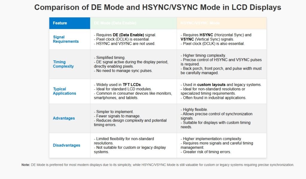
What Is the Difference Between DE Mode and HSYNC/VSYNC Modes?
| Feature | DE Mode | HSYNC/VSYNC Mode |
|---|---|---|
| Timing Complexity | Low | Medium to High |
| Required Signals | DE, DCLK | HSYNC, VSYNC, DCLK, (optional DE) |
| Application | Modern TFT LCD, high-speed panels | Custom timing, special layouts |
| Flexibility | Lower | Higher |
What Are the Key Timing Parameters and How Do Signal Timing Charts Guide LCD Configuration?

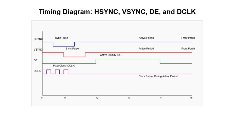
Timing parameters in RGB display modules define the flow and integrity of visual data. The active period is the time when valid pixel data is sent to the display. Blanking intervals—including the front porch and back porch—are periods without data transmission, letting the display controller prepare for new lines or frames. Sync pulse widths measure how long the HSYNC and VSYNC signals remain active, directly impacting how each row and frame are identified. Pixel clock frequency determines the speed of data transmission, ensuring the correct number of pixels are sent per second. Accurately setting these timing parameters keeps the LCD panel stable, maintains image quality, and prevents unwanted artifacts(How Do You Calculate the Dot Clock for an LCD Display?).
Display engineers and developers depend on signal timing charts to visualize the interaction between HSYNC, VSYNC, DE, and DCLK. These charts help interpret the structure of an entire video frame, showing when each signal is active or idle. By referencing timing diagrams, teams can confirm their RGB signal setup matches the LCD module’s requirements. Projects involving RGB888 or RGB565 color formats must ensure that the data is sent within the DE active period. Extracting parameters directly from the LCD datasheet is critical—reading the provided timing charts, identifying the values for each porch, sync width, and clock rate, then transferring these settings into the display controller(Color Depth Processing for LCD Panels with LED Backlighting).
Below is a signal timing chart that highlights the placement of the active period, blanking intervals, and sync pulses in a typical RGB LCD module:
| Parameter | Definition | Typical Example | Impact on Image |
|---|---|---|---|
| Active period | Valid pixel data | 800×480 pixels | Visible image area |
| Blanking interval | No data (front/back) | 40+88 pixels | Border/transition |
| Sync pulse width | HSYNC/VSYNC duration | 1-5 pixels/lines | Row/frame detection |
| Pixel clock freq | Data rate | 33.3 MHz | Image clarity |
What Do Active Period, Blanking Interval, Sync Pulse Width, and Pixel Clock Frequency Mean?
Active period is the exact window where the system transmits valid pixel data. Only during this time do pixels change on the display. The blanking intervals—divided into front porch and back porch—are the “gaps” before and after the active pixel data, allowing the system to prepare the next line or frame. Sync pulse width is how long the HSYNC or VSYNC signal stays active, which tells the controller when to reset the line or frame counter. Pixel clock frequency sets the speed at which data moves, directly controlling the resolution and refresh rate.
In real LCD projects, failing to match these parameters can cause screen tearing, shifted images, or black borders. For example, if the active period is too short, not all data reaches the screen; if the blanking interval is too long, you see black lines. Adjusting sync pulse width is key when working with panels from different suppliers, as even minor mismatches may create unstable rows or frames.
Below is a bullet list for fast review:
- Active period: Where valid pixel data is sent (image visible)
- Blanking interval: No data zone, system reset (transition/border)
- Sync pulse width: Duration of sync signals (line/frame separation)
- Pixel clock frequency: Speed of pixel transfer (resolution control)
How Do You Read and Interpret Timing Diagrams for RGB LCDs?
Timing diagrams are tools to visualize when and how each signal is activated. These charts display the relationship between HSYNC, VSYNC, DE, and DCLK across a frame. They clarify which part of the cycle transmits valid data and when the controller should reset or pause.
- Identify the active period—the rectangle where DE is high.
- Spot the front porch and back porch—blank areas before/after the active region.
- Measure the sync pulse widths—sections where HSYNC or VSYNC stay low or high, as shown in the diagram.
- Verify the pixel clock frequency matches the total horizontal and vertical timing.
How Is LCD Data Mapped to Timing Signals and Why Is Data Validity Essential?
LCD data—especially for formats like RGB888 and RGB565—must be perfectly synchronized with timing signals. The controller must send each RGB signal only during the DE active period. Sending data outside this window causes artifacts: lines, color blocks, or missing pixels.
Mapping data correctly prevents errors:
- In RGB888, each pixel uses 24 bits, requiring the controller to count data bits carefully.
- In RGB565, each pixel is 16 bits, so timing per pixel differs slightly.
- The display controller uses timing parameters (from datasheet) to set when each signal goes high or low, aligning the data with the DE window.
During setup, engineers extract all necessary timing details from the LCD datasheet. They calculate the total horizontal and vertical periods, set the correct clock speed, and program the display system accordingly.
Table mapping data to timing:
| Data Format | Bits per Pixel | DE Active Period | Required Clock Rate | Risk if Mismatched |
|---|---|---|---|---|
| RGB888 | 24 | Yes | High | Color shift, noise |
| RGB565 | 16 | Yes | Medium-High | Color banding, lines |
How Do Timing Errors Lead to Image Instability in RGB Displays?
| Artifact | Likely Timing Error | Parameter to Check | Example Fix |
|---|---|---|---|
| Flicker | Sync/clock mismatch | HSYNC, VSYNC, pixel clock | Adjust refresh settings |
| Distortion | Porch/sync width error | Front/back porch, sync | Tune porch/pulse widths |
| Ghosting | Timing/pixel response | Pixel clock, DE timing | Lower clock, use overdrive |
| Noise | Overclocked clock | Pixel clock frequency | Reduce clock rate |
| Blank screen | Severe timing failure | All timing signals | Check all parameters |
What Visual Artifacts Occur When Timing Parameters Are Incorrect?
Flicker is seen as rapid brightness changes, caused by unstable sync or pixel clock rates. Distortion appears as skewed or shifted images, often traced to front porch, back porch, or sync width missettings. Ghosting means old image trails linger after pixel changes, usually made worse by slow pixel response and mistimed DE or clock signals. Noise includes random lines, static, or color speckles—most often from a pixel clock that runs above the panel’s maximum spec. Blank screens result from missing sync pulses or data never entering the DE active period.
In practice, these problems show up during the first hardware bring-up or when switching between LCD modules with different timing requirements. Engineers often swap timing chart settings and check oscilloscope waveforms to diagnose and fix these artifacts.
- Flicker: Pixel update inconsistency, sync/clock mismatch
- Distortion: Misaligned lines/frames, wrong porch or sync width
- Ghosting: Slow transitions, timing mismatch
- Noise: Pixel clock overclocked
- Blank screens: No valid timing signals
How Are Timing Errors Linked to Specific Parameters and Signals?
Each image artifact points to a particular timing parameter or signal problem. Shortened porches often move image lines out of position, while a polarity error in the sync pulse can flip or invert the display. Pixel clock overclocking usually corrupts RGB data, causing noise or missing rows. When troubleshooting, teams look for these links:
- Shortened porches: Line misalignment
- Wrong polarity: Image flips or color inversion
- Overclocked pixel clock: Noise, missing data
- Incorrect sync width: Frame or line overlap
Real LCD projects require parameter tuning for each new panel. Engineers frequently check all values in the LCD datasheet, then match settings in the display controller to fix errors.
| Parameter Issue | Visual Effect | Best Solution |
|---|---|---|
| Short porch | Skewed image | Increase porch width |
| Wrong sync polarity | Flipped image | Change sync polarity |
| High pixel clock | Data noise | Lower clock frequency |
| Narrow sync pulse | Frame or line shifting | Use datasheet pulse width |
How Do Pixel Response and Timing Parameters Interact in LCDs?
Pixel response time is how fast a pixel changes color after receiving data. If the timing is too fast, pixels cannot keep up, which leads to flicker or ghosting. In graphic LCD modules, this is often noticeable with rapid animation or scrolling. Using overdrive techniques—where the controller briefly applies a stronger signal to help the pixel change faster—can reduce these effects.
When timing-induced delays exist, overdrive can make transitions look smoother. If the pixel response is naturally slow, adjusting the pixel clock lower or increasing the DE active period may help. Engineers sometimes test with patterns and measure the actual response to tune these values.
- Slow response time: Amplifies flicker or ghosting
- Overdrive technique: Speeds up transitions
- Timing interaction: Must match pixel speed and clock rate
| Issue | Effect | Practical Adjustment |
|---|---|---|
| Slow response | Flicker/ghosting | Use overdrive, slow clock |
| Mismatched timing | Instability | Align timing with response |
How Can Advanced Display Artifacts Like Ghosting, Mura, and Inversion Be Mitigated in RGB LCDs?
Advanced display artifacts—such as ghosting, mura, pixel inversion errors, and frame-rate flicker—can reduce the visual quality and reliability of RGB LCD modules. Ghosting is addressed by fine-tuning overdrive settings and optimizing the pixel clock. Mura, seen as uneven brightness or blotches, is minimized by calibrating uniform backlight timing to maintain backlight uniformity. For pixel inversion, the system alternates polarity each frame to prevent burn-in. This requires precise timing synchronization; if polarity changes fall out of sync, visible checkerboard patterns or additional flicker can result. Finally, frame-rate control—especially with temporal dithering—can introduce unwanted flicker if not perfectly aligned with VSYNC. Properly synchronizing the frame rate ensures smooth images and reduces visual disturbances(What are mura defects in LCDs?).
In real-world LCD engineering projects, these issues require hands-on adjustments, thorough testing, and careful reading of timing diagrams. Engineers must verify each mitigation technique directly on the hardware, often using oscilloscope checks and test patterns to ensure improvements.
Below is a troubleshooting table showing advanced artifact types and targeted solutions:
| Artifact | Main Cause | Mitigation Strategy | Key Signal/Parameter |
|---|---|---|---|
| Ghosting | Pixel lag, clock mismatch | Overdrive, pixel clock | DCLK, overdrive settings |
| Mura | Backlight non-uniformity | Calibrate backlight | Backlight timing |
| Pixel inversion | Polarity out-of-sync | Alternate polarity | Inversion, HSYNC/VSYNC |
| Checkerboard pattern | Polarity error, sync slip | Polarity-timing sync | Inversion signal |
| Flicker (dithering) | Frame-rate mismatch | VSYNC synchronization | Frame-rate, VSYNC |
How Can Ghosting and Mura Be Reduced in RGB LCD Displays?
Ghosting is caused by delayed pixel transitions, often made worse by a mismatched pixel clock or insufficient overdrive. Optimizing overdrive applies a stronger voltage during transitions, speeding up pixel response and making moving images clearer. Careful pixel clock tuning is necessary—too fast or too slow can amplify ghosting.
Mura refers to visible brightness irregularities or blotches. This is mitigated by calibrating the backlight timing to ensure consistent backlight uniformity. In hardware setups, engineers use uniformity test patterns and adjust backlight driving circuits to spread light evenly across the panel.
- Ghosting: Tune overdrive and adjust pixel clock
- Mura: Calibrate backlight timing for uniformity
How Does Pixel Inversion Prevent Burn-In and What Errors Can Occur?
Pixel inversion alternates the polarity of the drive signal to each pixel every frame or line. This process prevents burn-in—where a static image causes permanent marks on the display. Successful inversion requires perfectly synchronized timing with the rest of the display cycle. If timing slips or the inversion signal becomes unsynchronized, a visible checkerboard pattern or extra flicker will appear.
- Burn-in prevention: Alternate pixel polarity with each frame
- Timing sync: Match inversion with HSYNC/VSYNC
- Checkerboard/flicker: Check for polarity errors or sync slips
| Issue | Symptom | Solution |
|---|---|---|
| Inversion sync error | Checkerboard, flicker | Re-align polarity, sync signals |
| Missed inversion | Local burn-in | Review timing, hardware match |
How Does Frame-Rate Control Impact Flicker and Image Stability?
Frame-rate control uses methods like temporal dithering to increase perceived color depth by rapidly alternating subframes. If not synchronized with VSYNC, this technique can produce visible flicker or color instability. Synchronizing the frame-rate with VSYNC aligns updates to the display’s refresh, producing a steady, stable image. In practice, mismatched rates result in moving artifacts or unstable brightness—engineers must tune both controller and source to match exact refresh timing.
- Temporal dithering flicker: Caused by unsynced frame-rate
- Stability: Achieved by VSYNC synchronization
- Practical tuning: Match controller frame-rate with display refresh
| Error Type | Visual Effect | Recommended Fix |
|---|---|---|
| Dithering flicker | Visible flicker | Lock frame-rate to VSYNC |
| Frame-rate drift | Instability | Tune refresh and input timing |
How Do Environmental and Long-Term Factors Affect Timing Stability in RGB LCD Modules?
| Factor | Impact on Timing | Example Scenario | Mitigation/Best Practice |
|---|---|---|---|
| Temperature | Alters pixel response | Cold slows transitions | Adjust overdrive/clock |
| Voltage fluctuation | Varies timing accuracy | Sudden drop changes sync | Monitor, voltage regulation |
| Component aging | Drift in sync/timing | Old panel shows flicker | Schedule calibration |
| Timing tolerance | Acceptable variation | ±5% pixel clock, panel-based | Set margins, check datasheet |
How Do Temperature and Voltage Changes Influence LCD Timing?
Temperature effects can slow or speed up liquid crystal response. When displays operate in cold environments, pixels transition more slowly, leading to visible lag, ghosting, or flicker. Engineers often adjust overdrive settings or slow the pixel clock to match the slower pixel response. Voltage fluctuations may change the reference levels for signal timing, shifting sync pulses or data windows and causing instability(The Effect of Temperature on the Functional Performance of LCD Modules).
- Cold temperature: Slower transitions, need for overdrive tuning
- Voltage fluctuation: Risk of timing variation, sync errors
How Does Component Aging Affect Timing Accuracy and Sync Stability?
As LCD modules age, component aging reduces timing accuracy. Clock drift and signal degradation become more common, often showing up as increased flicker, unstable frames, or sync signal loss. Over time, even minor drift can cause significant display artifacts. Routine calibration—checking all timing parameters and adjusting them to specification—prevents long-term instability and extends display life(How to Master the LCD Aging Test Process?).
- Component aging: Increased drift, unstable sync signals
- Regular calibration: Maintains timing, reduces aging effects
| Aging Effect | Timing Symptom | Maintenance Action |
|---|---|---|
| Sync drift | Frame misalignment | Recalibrate, replace parts |
| Timing inaccuracy | Flicker, ghosting | Review all signal timings |
How Is Timing Tolerance Defined and Managed in LCD Design?
Timing tolerance is the acceptable range for each timing parameter (such as pixel clock or sync width) before image artifacts appear. Teams define these tolerances by testing LCD modules under real operating conditions. For instance, a ±5% variation in pixel clock might work for one display but not for another. By setting clear timing margins and referencing the LCD datasheet, engineers ensure the display remains stable even as conditions change or components age.
- Timing tolerance: Set per panel and use-case, reference datasheet
- Pixel clock variation: ±5% is common, but application dependent
- Stability assurance: Continuous monitoring, routine checks
| Parameter | Typical Tolerance | Dependency |
|---|---|---|
| Pixel clock | ±5% | Panel specification |
| Sync pulse width | ±2 clock cycles | Controller accuracy |
How Is Timing Compatibility Achieved Across Different LCD Panel Types and Resolutions?
Timing compatibility across different LCD panel types requires a flexible approach to signal parameters and careful use of driver frameworks. Each display technology—such as TN, IPS, and TFT—has unique timing requirements due to differences in pixel structure and response speed. For instance, IPS panels often need longer porches to accommodate slower pixel transitions, while TN panels can operate with shorter timing margins(Difference between IPS TFT and TN TFT).
To support multiple panel types in the same system, engineers use universal driver frameworks that allow easy adaptation of timing configurations. For example, the Linux fb_videomode structure is designed to support a range of resolutions, frame rates, and panel behaviors. These drivers abstract hardware differences, letting the system apply optimal timing settings automatically.
Resolution and frame rate also impact timing. Higher resolutions demand a faster pixel clock and tighter control of sync timing. When frame rates change—such as moving from 60 Hz to 120 Hz—engineers must adjust porch durations and sync pulse widths to ensure data integrity and prevent artifacts. Balancing these factors maintains panel compatibility and image stability, even as requirements shift.
Below is a comparison table of LCD panel types and their typical timing parameters:
| Panel | Response Speed | Typical Porch Duration | Sync Width Requirement |
|---|---|---|---|
| TN | Fast | Short | Narrow |
| IPS | Slow | Long | Wider |
| TFT | Medium | Medium | Medium |
How Do Timing Requirements Differ Across LCD Panel Types?
TN, IPS, and TFT panels each have unique timing needs based on their internal structure and response speed. TN panels allow shorter porches and narrower sync signals because of their fast pixel response. IPS panels need longer porches and wider sync pulses to accommodate slower transitions, preventing ghosting or misalignment. TFT panels usually fall in between, requiring moderate adjustments.
- TN: Short porches, quick sync, fast display
- IPS: Longer porches, wide sync, slower but higher-quality image
- TFT: Balanced timing and sync settings
How Are Timing Configurations Standardized for Multi-Panel Systems?
Universal driver frameworks abstract hardware differences, letting software configure optimal timing for any panel. fb_videomode in Linux is an example: it allows the OS or application to specify resolution, porch, sync, and pixel clock values for any supported LCD module. With this approach, teams avoid hard-coding timing, making it easier to swap panels or support upgrades.
- Timing standardization: Managed by universal frameworks
- fb_videomode: Enables flexible multi-panel support
- Hardware abstraction: Simplifies compatibility
| Framework/Driver | Supported Parameter | Benefit |
|---|---|---|
| fb_videomode | Resolution, porch, sync, clk | Panel independence |
| Custom driver | Specific to hardware | Tuned for exact panel |
How Are Timing Settings Adapted for Different Resolutions and Frame Rates?
Higher resolutions require a faster pixel clock and more precise sync timing. As frame rates rise—such as from 60 Hz to 120 Hz—timing margins shrink, making porch and sync settings even more critical. Engineers must re-calculate porch durations and sync pulse widths for each new mode, always verifying signal integrity with test images and measurement tools.
- High resolution: Needs faster pixel clock
- Frame rate change: Adjust porch and sync for each mode
- Timing adaptation: Essential for stable, artifact-free images
| Setting | 60 Hz Example | 120 Hz Example |
|---|---|---|
| Pixel clock | Moderate | Much faster |
| Porch duration | Longer | Shorter |
| Sync width | Standard | Tighter |
FAQ
How Can You Ensure Signal Timing Matches LCD Datasheet Specifications?
Check datasheet values for HSYNC, VSYNC, DE, and DCLK. Use an oscilloscope to verify pulse widths and porch durations.
What Happens If Signal Timing Is Not Adjusted for Low-Power Modes?
Incorrect timing in low-power modes causes flicker or blank screens. Adjust pixel clock and sync signals to match reduced power settings.
How Do You Prevent Timing Issues in Outdoor LCD Displays?
Outdoor displays face temperature swings affecting pixel response. Calibrate overdrive and pixel clock for extreme conditions.
Can Software Tools Simulate LCD Timing Before Hardware Testing?
Software like timing diagram editors simulates signal timing charts. This predicts artifacts before physical testing.
How Do You Handle Timing for Custom LCD Panels?
Custom panels need unique timing parameters. Analyze datasheet specs and test with logic analyzers to set accurate sync signals.