Automotive LCDs face strict EMI/EMC rules to prevent interference and ensure reliability. These rules cover emissions, immunity, and how displays work with other car electronics.
EMI Basics: EMI is unwanted electrical noise that can make screens flicker or disrupt car systems. LCDs must limit this noise.
EMC Basics: EMC means displays work properly while ignoring interference from other devices. Cars need this for safety.
Key Standards: Four main rules apply:
- CISPR 25 controls radio noise from displays
- ISO 11451/11452 test immunity to wireless signals
- ISO 7637 checks handling of power spikes
- ISO 10605 verifies protection against static shocks
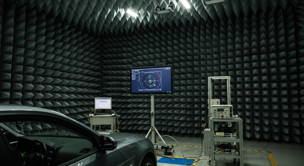
Engineers use special layouts, metal shields, and filters to meet these rules. The goal is displays that work perfectly in cars full of electronics. Bad EMC can cause dangerous display failures in cars. Proper design prevents these problems before production. Every display undergoes strict EMC checks using special chambers and equipment. This ensures real-world performance matches lab results. Good EMC design costs more upfront but prevents expensive recalls later. It’s cheaper than fixing problems after production.
HUA XIAN JING has cooperated with many electric car brands in China to provide them with customized products for car navigation screen and car entertainment information screen, we have professional labs to check the qualification of LCD screen, contact us to visit HUA XIAN JING’s production factory!
What Are the Key EMI/EMC Standards for Automotive LCD Displays?
The key standards are CISPR 25, ISO 11451/11452, ISO 7637, and ISO 10605, which address emissions, immunity, transient disturbances, and ESD for LCD displays in vehicles.
Automotive LCD displays must meet CISPR 25 for radio disturbance limits, focusing on 30 MHz to 1 GHz to prevent interference with vehicle electronics. ISO 7637 tests ensure displays withstand voltage spikes from alternators or ignition systems, with pulses up to 100V/1ms simulating real-world conditions.
- CISPR 25: Limits emissions in peak/average modes across AM/FM bands. Test setups use 50Ω antennas at 1m distance.
- ISO 7637-2: Tests include Pulse 3a/b (12V systems) and Pulse 5a (24V systems), with 100Ω/50μs coupling networks.
How Does ISO 11451/11452 Ensure Radiated Immunity for LCD Displays?
These standards test LCD resilience to 20–2,000 MHz radiated fields, simulating AM/FM/TV broadcast interference.
Tests use TEM cells or anechoic chambers with 200V/m field strength. Displays must operate without flickering or data corruption during exposure.
- ISO 11452-4: Uses bulk current injection (BCI) at 1–400 MHz with 60mA current levels.
- Test setups place displays 0.5m from antennas, scanning frequencies at 1% steps.
Why Is ISO 10605 Critical for Automotive LCD ESD Protection?
It simulates 15kV human-body-model discharges to ensure LCDs survive static shocks during assembly or use.
Discharge points include touchscreen edges and metal bezels. Designs use TVS diodes with <1ns response time to divert ESD energy.
- Contact discharges: ±8kV (direct) and ±15kV (air).
- RC networks on flex cables limit charge injection to driver ICs.
What PCB Design Techniques Reduce EMI in Automotive LCDs?
Ground planes, shielding cans, and filtered connectors cut noise by 40dB in critical bands.
4-layer PCBs with <5mm trace spacing prevent crosstalk. Ferrite beads on power lines block high-frequency noise.
- Shielding: 0.1mm aluminum cans with 360° contacts reduce emissions by 30MHz–1GHz.
- Filters: π-type LC circuits attenuate noise >50dB above 100MHz.
How Do Transient Disturbances Affect LCD Power Supplies?
ISO 7637-2 pulses can reset display drivers unless LDOs with 60dB PSRR are used. TVS diodes clamp transients below 40V, while 10μF tantalum capacitors absorb energy.
- Pulse 1: -100V/2Ω simulates load-dump.
- Pulse 2a: +50V/0.5Ω mimics inductive kick.
What Are the Emission Hotspots in LCD Flex Cables?
Unshielded flex cables radiate at 120MHz–600MHz due to high-speed LVDS signals. Twisted pairs and grounded shields cut emissions by 20dB. EMI gaskets at connectors block leakage.
- Impedance: 100Ω differential pairs minimize reflections.
- Shielding: Copper foil wraps with <2mm gaps prevent slot antennas.
How to Test LCD Panels for CISPR 25 Compliance?
Use peak detectors in 30–300MHz scans, with displays at max brightness. Test distances are 1m for components and 3m for full dashboards. Absorber mats suppress reflections.
- RBW: 120kHz for peaks, 1MHz for averages.
- Antennas: Biconical (30–300MHz) and log-periodic (300–1GHz).
What Layout Rules Prevent EMI in LCD Driver Circuits?
Keep analog/digital grounds separate and use star-point routing for power. 2oz copper planes reduce impedance. 0402 capacitors placed <3mm from ICs decouple noise.
- Via stitching: 1 via/5mm along ground edges.
- Trace length: <25mm for clock lines to limit ringing.
How to Design Automotive LCDs for Optimal EMC Performance?
Use PCB layout optimization, EMI shielding, grounding/filtering strategies, and decoupling capacitors to meet automotive EMC requirements.
Short trace lengths and separated ground planes reduce crosstalk in LCD driver circuits. Conductive gaskets and shielded enclosures block radiated emissions from flex cables.
- Trace spacing: ≥3× trace width to prevent coupling.
- Ground planes: 4-layer PCBs with <5mm via spacing for low impedance.
What PCB Layout Rules Reduce EMI in Automotive LCDs?
Route high-speed signals first, keep traces short, and isolate analog/digital grounds with split planes.
Place LCD drivers near connectors to minimize trace length. Use 45° bends (not 90°) to avoid impedance discontinuities.
- Clock signals: Length-matched ±5mm to prevent skew.
- Power routing: Star topology with <100mΩ loop resistance.
Which Shielding Methods Work Best for Automotive LCDs?
Metal enclosures, conductive coatings, and EMI gaskets suppress emissions by 20–40dB.
Apply nickel-coated copper tape on flex cables. Use spring fingers for continuous shielding at seams.
- Shielding effectiveness: ≥60dB at 1GHz with 0.2mm aluminum.
- Gasket compression: 30% deflection ensures contact resistance <10mΩ.
How to Ground and Filter LCD Electronics for EMC?
Use single-point grounding and LC filters on power/display lines to block noise.
Connect chassis ground to PCB ground via low-inductance straps. Place ferrite beads on LVDS cables.
- Filter cutoff frequency: 10MHz for 1nF+10μH LC filters.
- Ground loops: Avoid by keeping wires <50mm between grounds.
Why Are Decoupling Capacitors Critical for LCD EMC?
They suppress power rail noise from vehicle transients, with 100nF+10μF combinations covering 10kHz–100MHz.
Place 0402 capacitors within 3mm of IC pins. Use X7R dielectric for stable capacitance under voltage.
- ESR: <100mΩ for 100nF caps at 100MHz.
- Resonance: Avoid by mixing 0.1μF ceramic + 10μF tantalum.
How to Isolate Noisy Circuits in LCD Driver PCBs?
Use moats (2mm gaps) and shielded compartments to separate motor drivers from LVDS signals.
Route noisy traces on inner layers with ground shields above/below.
- Isolation impedance: >1kΩ at 100MHz with 4mm keep-out zones.
- Cross-talk reduction: 30dB with guard traces between signals.
What Filtering Is Needed for LCD Interface Cables?
Common-mode chokes and π-filters cut noise by 15dB on LVDS/HDMI lines.
Select 100Ω chokes for LVDS pairs. Place filters <10mm from connectors.
- Insertion loss: >40dB at 500MHz with 2-stage filters.
- Capacitor values: 1nF (Cx) + 100pF (Cy) for EMI suppression.
How to Test Shielding Effectiveness in LCD Modules?
Use TEM cells to measure radiated emissions with/without shields at 30MHz–1GHz.
Scan with 1V/m field strength and compare peak amplitudes in shielded vs. unshielded tests.
- Test setup: IEC 61000-4-21 with 0.8m × 0.8m cell aperture.
- Pass criteria: <30dBμV/m at 200MHz for CISPR 25 Class 5.
What Are the Worst-Case EMC Scenarios for Automotive LCDs?
Engine ignition pulses (ISO 7637-2) and AM radio interference (CISPR 25) cause most failures.
Test with Pulse 3b (-150V) and 200V/m RF fields to verify robustness.
- Ignition pulses: 2ms duration, 2Hz repetition.
- AM band immunity: 1MHz steps at 90% modulation.
What EMI Issues Affect Automotive LCD Performance?
Screen flickering and interference with vehicle systems are the most common EMI problems in automotive LCDs.
High-frequency noise from switching regulators causes visible flicker at 100–300Hz. Unshielded display cables can disrupt CAN bus signals with 10–50mV induced noise.
- Flicker frequency: Matches PWM backlight modulation (typically 200–1000Hz).
- CAN bus sensitivity: Fails at ±500mV noise (ISO 11898-2).
How Does EMI Cause Screen Flickering in Automotive LCDs?
Power supply noise and radiated coupling distort display signals, creating visible flicker or image tearing.
Ground bounce in driver ICs shifts TFT pixel voltages by ±5%, causing brightness variations. LVDS signal jitter exceeding 0.3UI corrupts video data.
- Noise threshold: >50mVpp on 3.3V LCD power rails triggers flicker.
- Mitigation: Ferrite beads (600Ω @ 100MHz) + 10μF MLCCs stabilize power.
How Can LCDs Interfere with Vehicle Control Systems?
EMI emissions from LCDs can disrupt ECU communications (CAN/LIN) or sensor signals (e.g., radar, cameras).
30–300MHz display emissions couple into ADAS camera cables, reducing SNR by 6dB. Improper grounding creates ground loops that distort throttle position sensor readings.
- Critical frequencies: 77GHz radar affected by harmonic emissions from LVDS clocks.
- Shielding requirement: >40dB attenuation at 1GHz for ISO 11452-2 compliance.
What Design Fixes Prevent LCD-Induced ECU Interference?
Shielded flex cables and spread-spectrum clocking reduce radiated emissions below CISPR 25 limits.
Copper-mesh wraps on cables cut common-mode noise by 15dB. SSCG (±1% modulation) lowers peak EMI at clock harmonics.
- Cable shielding: 360° coverage with <2Ω/sq surface resistance.
- SSCG settings: 30kHz modulation rate for LVDS 650MHz clocks.
How to Diagnose EMI-Related LCD Flicker?
Use oscilloscopes to check power ripple (<20mVpp) and jitter (<0.15UI) on display interfaces.
Near-field probes locate 50–200MHz noise sources near driver ICs. Spectrum analyzers confirm emissions at FM radio bands (88–108MHz).
- Probe positioning: 5mm spacing from PCB traces for accurate readings.
- Ripple limits: 3.3V rail: ±50mV, 12V rail: ±200mV.
Why Do Automotive LCDs Fail ESD Tests?
Poor ESD protection on touchscreen edges and connectors allows ±15kV discharges to reset driver ICs.
TVS diodes with <1ns response must protect I2C/SPI lines. Zigzag PCB layouts increase discharge paths to >20mm.
- ESD test points: Contact ±8kV, Air ±15kV (ISO 10605).
- TVS specs: 3A peak current, 5pF capacitance.
What LCD Design Errors Increase EMI Risks?
Long unshielded traces, split ground planes, and missing ferrites raise emissions 10–20dB.
>50mm unfiltered power traces act as antennas. Gaps in shielding cans create slot resonances at 800MHz–2GHz.
- Trace length limit: λ/20 at 300MHz = 25mm max.
- Shielding gaps: Must be <λ/10 at highest frequency (e.g., 3mm @ 1GHz).
How Does Temperature Affect LCD EMI Performance?
Cold temperatures increase capacitor ESR, reducing filtering effectiveness by 30% at -40°C.
X7R capacitors lose 60% capacitance at 125°C. Conductive adhesives crack below -30°C, breaking shield bonds.
- Capacitor derating: 1μF @ 25°C → 0.4μF @ 85°C.
- Shield bond resistance: Must stay <0.1Ω from -40°C to 105°C.
What Are the Worst-Case EMI Scenarios for LCDs?
Engine start pulses (ISO 7637-2 Pulse 1) and AM radio interference (CISPR 25 Band II) cause most failures.
Load dump (-100V) can latch up LCD driver ICs. 88–108MHz FM band noise creates horizontal streaks on displays.
- Load dump test: -100V/2Ω, 400ms duration.
- FM immunity: 20V/m @ 98MHz, 80% AM modulation.
What Are the Biggest EMC Challenges When Integrating Automotive LCDs?
The key challenges are structural-electrical coordination and compatibility with existing vehicle electronics to prevent EMI issues.
Metal bezel designs must balance aesthetics and EMC performance, often requiring conductive gaskets at display edges. Infotainment system integration demands <30dB crosstalk between LCD and audio circuits.
- Bezel-shield gap: Must be <1mm with finger stock gaskets (0.3N/mm² contact pressure)
- Crosstalk limits: -70dB @ 1MHz between LVDS and MOST150 optical links
How Should Structural and EMC Engineers Collaborate on LCD Designs?
They must jointly optimize shielding geometry and material selection from the first CAD models (“EMC by Design”).
Early 3D EM simulations predict resonance hotspots in display cavities. Mechanical teams must reserve 0.5mm tolerance zones for conductive gaskets around LCD perimeters.
- Simulation accuracy: ±3dB vs measured up to 6GHz using hybrid FEM/MoM solvers
- Gasket compression: Requires 20-30% deflection of nickel-coated silicone cores
What Integration Techniques Prevent LCD EMI in Vehicle Architectures?
Use optical isolation for video links and zone-based grounding to contain high-current return paths.
Fiber-optic video interfaces eliminate ground loops that cause 30-100MHz emissions. Separate 12V power domains for displays and ECUs reduce conducted noise coupling.
- Zone grounding: Maximum 2mΩ resistance between local ground points
- Optical isolation: 150Mbps LVDS over POF with >60dB common-mode rejection
How to Ensure LCD Compatibility With Power Electronics?
Implement triple-stage filtering on power inputs and active noise cancellation for PWM backlight drivers.
Coupled inductors cancel 100-500kHz switching noise from alternators. Synchronous buck converters with <5ns edge rates reduce high-frequency emissions.
- Filter topology: 10μH + 100μF + 1μF achieves -40dB attenuation @ 1MHz
- PWM backlight: Spread spectrum modulation with ±5% frequency dithering
What Mechanical Details Impact LCD EMC Performance?
Display mounting method and aperture design significantly affect shielding effectiveness.
Spring-loaded shield contacts must maintain <10mΩ resistance across vehicle vibration profiles. Display window aspect ratios influence cavity resonance modes.
- Resonance formula: For 16:9 displays, first mode occurs at 1.5× width (mm) = λ/2 (GHz)
- Vibration testing: 1000 cycles at 15G RMS must not degrade shield contact
How to Handle High-Speed Data Lines Near LCDs?
Route Ethernet/USB 3.0 traces on buried layers with guard traces and differential pair length matching.
Embedded coaxial structures maintain 90Ω impedance for Gigabit video links. Via stitching every λ/10 prevents shield leakage.
- Layer stackup: 0.1mm prepreg between signal and ground layers
- Length matching: ±50ps skew tolerance for 5Gbps links
What Thermal Considerations Affect EMC Performance?
Temperature cycling can break shield bonds and alter filter component values.
Conductive adhesives must withstand -40°C to 105°C without cracking. Ferrite beads lose 30% impedance at high temperatures.
- Adhesive specs: >5N/mm peel strength after 1000 thermal cycles
- Component derating: X7R capacitors lose 50% capacitance at temperature extremes
How to Verify EMC During LCD Prototyping?
Combine pre-compliance scans (30MHz-1GHz) with time-domain reflectometry for interface validation.
Near-field probes identify local emission hotspots before full chamber tests. TDR measurements verify impedance continuity in shielded flex cables.
- Scan resolution: 1cm grid with 5mm probe height
- TDR specs: ±5% impedance tolerance, <10ps rise time
What Are Critical but Often Overlooked Integration Points?
Connector shield termination and display dimming circuits frequently cause late-stage EMC failures.
360° connector shields require dual-contact springs for reliable bonding. Analog dimming lines need π-filters to prevent AM band interference.
- Connector resistance: <5mΩ per mating cycle
- Filter values: 100Ω + 100pF for 0-5V dimming lines
What Advanced Techniques Optimize EMC in Future Automotive LCDs?
Next-gen solutions include high-layer PCBs, nano-coated shields, and AI-driven EM simulations to balance performance and cost.
12-layer HDI PCBs with 1µm copper roughness reduce skin effect losses by 15% at 10GHz. Graphene-doped gaskets provide 80dB shielding while being 40% thinner than traditional materials.
- Stackup innovation: 3μm dielectric spacing between shielded signal layers
- Nano-coating performance: 0.1Ω/sq surface resistance with 5µm thickness
How Can PCB Stackups Improve LCD EMC Compliance?
Buried capacitance layers and offset striplines cancel noise without adding components.
0.5mm prepreg cores with 2.2Dk material minimize interlayer crosstalk. 45° zigzag ground vias suppress resonant cavity modes in large displays.
- Buried capacitance: 5nF/cm² between power-ground pairs
- Via spacing: λ/20 at highest frequency (e.g., 1.5mm @ 10GHz)
What New Shielding Materials Work for Automotive LCDs?
Metamaterial absorbers and magnetic nanocomposites offer lighter, stronger alternatives to metal shields.
Frequency-selective surfaces block specific radar bands (24/77GHz) while being transparent to display signals. Nickel-zinc ferrite tapes absorb 300MHz-3GHz noise at 0.3mm thickness.
- Metamaterial specs: -30dB absorption at target frequencies
- Tape permeability: μ=300 @ 1GHz with 5% weight savings
How to Future-Proof LCDs Against New EMC Standards?
Reconfigurable filter networks and software-defined impedance matching adapt to regulation changes.
FPGA-controlled LC arrays automatically tune to new frequency bands. Dynamic termination resistors compensate for cable length variations.
- Tuning range: 1MHz-6GHz via 64-step digital capacitors
- Response time: <100µs for real-time adaptation
What Manufacturing Advances Reduce EMC Defects?
3D-printed shielding structures and automated EMC inspection slash production failures by 75%.
Conductive aerosol jet printing builds custom shield geometries in assembly lines. Millimeter-wave scanners detect shield gaps <50µm.
- Print resolution: 10µm conductive traces
- Inspection accuracy: ±0.05dB shielding deviation
How Do New Standards Impact LCD EMC Design?
UN R10 Rev.8 and CISPR 36 now require 77GHz radar immunity and 2GHz emissions control.
Absorptive liners behind displays prevent radar false positives. Substrate-integrated waveguides route high-speed signals without leakage.
- Radar test levels: 200V/m @ 76-81GHz
- Waveguide specs: 0.5dB/mm loss up to 40GHz
What Breakthroughs Are Coming in Automotive LCD EMC?
Quantum dot shielding and plasmonic filters may enable EMC-compliant transparent displays by 2030.
Tunable metamaterials could dynamically block specific interference bands. Self-healing conductive polymers may repair shield damage automatically.
- QD shielding: 90% transparency with 40dB attenuation
- Self-healing: <24hr recovery after 5mm scratch damage
What EMI/EMC Challenges Do LCDs Face in Electric/Autonomous Vehicles?
High-voltage noise and connected vehicle interference create unique EMC hurdles for future automotive displays.
800V EV architectures generate 100kHz-10MHz common-mode noise requiring reinforced isolation barriers in LCD power supplies. 77GHz radar systems demand 60dB shielding to prevent display-induced false echoes.
- Isolation requirements: 5kV DC/2.5kV AC reinforced insulation per IEC 60664-1
- Radar shielding: Aluminum-coated PCBs with <0.1mm apertures block 76-81GHz
How Does High-Voltage EV Electronics Affect LCD EMC?
400-800V battery systems create 50-100V/µs switching transients that couple into display circuits.
Galvanic isolation using digital isolators prevents ground loops. Triple-shielded flex cables maintain >40dB rejection against inverter noise.
- Isolator specs: 150Mbps LVDS with 10kV/µs CMTI
- Cable construction: Foil+braid+overbraid with <2Ω/m transfer impedance
How to Future-Proof LCDs for V2X Communications?
Ultra-low emission drivers and 5.9GHz notch filters prevent interference with DSRC/C-V2X safety channels.
Spread-spectrum timing reduces fundamental clock emissions by 18dB. LTCC filters provide 40dB rejection at 5.85-5.925GHz.
- Clock dithering: ±2% modulation at 1kHz rate
- Filter specs: 0.5dB passband ripple, <2ns group delay
What Autonomous Vehicle EMC Requirements Impact LCDs?
ISO 21498 mandates <1µV/m emissions in 1-6GHz bands critical for autonomous sensor fusion.
Buried power planes and coplanar waveguides reduce reference plane resonances. Ferrite-loaded adhesives suppress GHz-range cavity modes.
- Layer stackup: 2oz copper with 0.2mm dielectric spacing
- Adhesive properties: μ”=15 @ 2GHz, tanδ<0.02
How Do EV Charging Systems Affect LCD EMC?
150kHz-30MHz conducted emissions from chargers require three-stage filters on display power inputs.
Common-mode chokes with 100mH inductance block asymmetric noise. X2Y capacitors provide balanced-to-ground filtering.
- Filter topology: 1μF-10μH-0.1μF with <1nH ESL
- Choke specs: 100Ω @ 1MHz, 5A DC bias current
What New Materials Enable EMC-Compliant Transparent Displays?
ITO-alternatives like silver nanowires maintain >80% transparency while providing 40dB shielding.
Mesh patterns with 5μm line width achieve 10Ω/sq without visible artifacts. Electrochromic layers dynamically adjust shielding as needed.
- Optical performance: <2% haze, >90% CRI
- Switching speed: 100ms transition between shielded/unshielded states
What Are Emerging Standards for AV/EV LCD EMC?
UNECE R10.06 now covers 76-81GHz radar immunity and 5G-V2X coexistence requirements.
Multi-physics simulations must verify <0.1°C thermal impact from shielding solutions. Time-domain EMC testing validates transient immunity up to 200V/ns.
- Test levels: 600V/m pulsed RF, 25kV ESD
- Simulation requirements: CST/FEKO with <5% margin of error
Related Articles:
What Is Circular Polarization and How Does It Improve LCD Displays?
What Is Embedded DisplayPort (eDP) and Why Is It Used in Modern Devices?
What’s the Key Difference Between DVI-I and DVI-D Connectors?
How Do In-Cell and On-Cell Touch Technologies Differ in Phone LCDs?
The Effect of Temperature on the Functional Performance of LCD Modules
FAQ
What is the difference between EMI and EMC in automotive display design?
EMI (Electromagnetic Interference) refers to unwanted electrical noise that can disrupt display functions, while EMC (Electromagnetic Compatibility) ensures displays neither emit nor are susceptible to such interference. In automotive applications, EMC is the broader discipline that includes both controlling emissions (EMI) and ensuring immunity to external interference.
How do EMC requirements for automotive displays differ from consumer electronics?
Automotive displays must withstand electromagnetic fields up to 100 V/m while maintaining visual performance, compared to just 3-10 V/m for consumer electronics. They also require compliance with specialized standards like CISPR 25 and ISO 7637, plus testing across extreme temperature ranges (-40°C to 105°C) and humidity levels not required for consumer products.
What are the most common EMC failure points in automotive LCD designs?
The most common EMC failure points include unshielded flexible flat cables (FFCs) acting as antennas, inadequate decoupling near timing controllers, ground loops between display modules and vehicle chassis, and insufficient filtering on backlight power supplies. These issues typically manifest as screen flickering, color distortion, or complete display failure during EMC testing.
How do touchscreen interfaces affect EMC compliance in automotive displays?
Touchscreen interfaces introduce additional EMC challenges due to their capacitive sensing layers, which can both emit and receive electromagnetic interference. These interfaces require specialized shielding techniques like ITO coatings with controlled surface resistance (10-50 Ω/sq) and dedicated ground planes to maintain touch accuracy during exposure to electromagnetic fields while preventing emissions that could affect nearby vehicle systems.
What EMC considerations are unique to OLED displays in automotive applications?
OLED displays present unique EMC challenges due to their high-frequency pixel driving circuits (operating at 120-240 Hz) and sensitivity to power supply variations. They require specialized power filtering with ultra-low ESR capacitors, enhanced shielding against UV/IR interference that can degrade organic materials, and additional protection against voltage transients that can significantly reduce display lifespan compared to LCD technology.