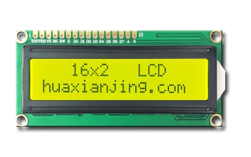
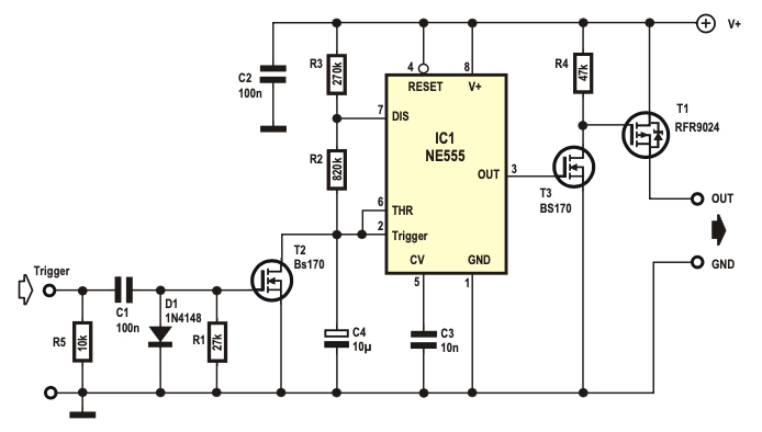
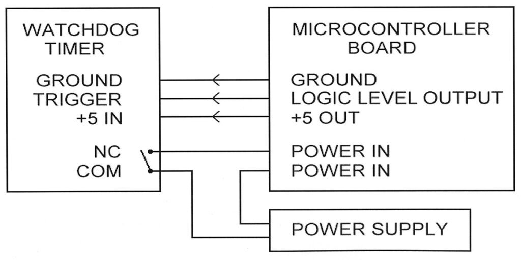
A watchdog timer monitors periodic signals from an LCD controller to detect unresponsive state changes. It triggers a reset action when those signals stop arriving within a configured timeout, restoring the display to a known-good state.
During normal operation, the firmware kicks the watchdog after each framebuffer update or status register write to confirm display activity. Designers set the timeout slightly above the panel’s longest refresh interval—like 16 ms for a 60 Hz screen—to avoid false resets.
If the LCD controller fails to service the timer before the timeout, the watchdog issues a non-maskable interrupt or hardware reset to reinitialize the module. This approach ensures that the LCD never remains stuck showing corrupted or stale data after a controller hang.
How Do Watchdog Timers Ensure Reliable LCD Monitoring?
Watchdog timers ensure reliable LCD monitoring by detecting unresponsiveness and initiating resets. They maintain system stability through periodic updates and error recovery.
The watchdog timer monitors signals from the LCD controller, such as frame buffer updates or status register writes. These signals, known as “kicking” the watchdog, reset the timer to prevent unwanted resets. The frequency of these updates aligns with LCD operations, like refresh cycles or data writes, ensuring continuous oversight. Hardware-based watchdog circuits operate independently, offering robust reliability, while software watchdogs depend on system stability, which may introduce risks in high-load scenarios.
- Periodic Updates: The LCD controller sends signals at intervals tied to refresh rates (e.g., 60 Hz for standard displays) to reset the watchdog timer. Missing a signal beyond the timeout interval (e.g., 1-5 seconds) triggers a response.
- Timer Monitoring: Hardware WDTs use dedicated watchdog ICs to track updates, consuming minimal power (e.g., 10-50 µA). Software WDTs, integrated into the MCU, rely on system interrupts, which may fail under heavy CPU load.
- Timeout and Reset: Upon timeout, the WDT issues a reset signal, either system-wide or specific to the LCD module. Resets typically complete within 100-500 ms, restoring display functionality.
- Error Recovery: Post-reset, the system reverts to a known state, re-establishing communication protocols (e.g., I2C or SPI) with the LCD to ensure accurate data display.
What Happens If a Watchdog Timer Fails to Reset the LCD System?
A watchdog timer failure may leave the LCD system unresponsive, risking display errors or data loss. The system requires fallback mechanisms to mitigate such risks.
Watchdog functionality depends on proper configuration and reliable hardware. A failure might occur due to misconfigured timeout intervals or faulty watchdog chips, leading to persistent display issues. To address this, developers implement redundant monitoring circuits or software watchdogs to ensure continuous operation. These backups maintain system reliability by triggering alternative recovery paths if the primary watchdog fails.
- Failure Scenarios: A watchdog timer IC may fail due to power surges, exceeding its voltage rating (e.g., 3.3V-5V). Software watchdogs may stall if the MCU crashes, halting interrupt signals.
- Fallback Mechanisms: Redundant hardware watchdogs use separate comparator timers to monitor the primary WDT. Software monitoring tools log errors, enabling manual intervention within 1-2 minutes of failure.
- Recovery Paths: Systems employ secondary reset lines to bypass a failed WDT, ensuring the LCD module resumes operation. Data integrity is preserved through buffered writes, preventing corruption during recovery.
How Should You Configure a Watchdog Timer for LCD Applications?
Proper configuration of a watchdog timer ensures reliable LCD operation by balancing fault detection and system stability. It requires setting an appropriate timeout period and selecting the right operation mode.
The watchdog timer must be tailored to the LCD’s refresh cycle, such as 60Hz (~16ms), to avoid false resets while catching faults quickly. Developers choose between timeout mode, windowed mode, or Q&A mode based on the application’s needs, ensuring the timer aligns with update intervals and system demands. Incorrect settings can lead to false triggers or missed faults, disrupting display accuracy.
- Timeout Period Selection: The timeout must exceed the LCD’s longest update cycle (e.g., 50ms for a low-refresh display) with a safety margin. A 100ms timeout accommodates delays while detecting hangs within 0.1-0.2 seconds.
- Operation Modes:
- Timeout Mode: Resets after a fixed period (e.g., 100ms) if no kick signal is received. Simple but prone to false resets during heavy loads.
- Windowed Mode: Requires kicks within a time window (e.g., 50-75ms) to avoid resets. It prevents premature or late updates, ideal for stable LCD modules.
- Q&A Mode: The MCU must respond correctly to a challenge query, enhancing fault detection for critical systems. It increases complexity but improves reliability.
- Balancing Sensitivity: A short timeout (e.g., 20ms) risks false triggers during normal frame buffer updates, while a long timeout (e.g., 500ms) delays fault detection. Testing under maximum load ensures optimal settings.
					// Example: Configuring a watchdog timer for an LCD application (Arduino)
#include <avr/wdt.h>

void setupWatchdog() {
  // Set timeout to 100ms (WDTO_120MS for Arduino)
  wdt_enable(WDTO_120MS);
  // Configure windowed mode (example pseudo-code for advanced MCUs)
  // WDT_WindowMode(50, 75); // Kicks allowed between 50-75ms
}

void loop() {
  // Simulate LCD frame update every 50ms
  updateLCDBuffer(); // Update frame buffer
  wdt_reset();       // Kick the watchdog
  delay(50);
}
What Are the Risks of Misconfiguring a Watchdog Timer in LCD Systems?
Misconfiguring a watchdog timer can cause unwanted resets or undetected faults, leading to display errors or system instability. Proper testing and fallback options mitigate these risks.
A timeout period set too short may reset the system during normal refresh cycles, while a period too long delays fault detection, risking data corruption. Developers use load testing and redundant monitoring to ensure the timer performs reliably under varying conditions. These measures maintain system stability and protect LCD functionality.
- Risk of Short Timeouts: A 20ms timeout may trigger resets during 60Hz refresh cycles (16.67ms), disrupting data writes. Testing with maximum refresh rates (e.g., 120Hz) avoids this issue.
- Risk of Long Timeouts: A 1-second timeout delays detection of MCU hangs, potentially freezing the LCD display. A 100-200ms range balances speed and stability.
- Fallback Options: Software watchdogs monitor the primary hardware WDT, logging errors if resets occur unexpectedly. Redundant timers ensure continued operation if the primary WDT fails.
- Testing Protocols: Simulate high CPU loads (e.g., 90% utilization) to verify the timer’s behavior. Adjust the timeout interval based on observed update delays (e.g., 10-20ms variability).
					// Example: Fallback software watchdog (pseudo-code for redundancy)
void softwareWatchdog() {
  static uint32_t lastKick = 0;
  if (millis() - lastKick > 150) { // Check if 150ms elapsed
    logError("Watchdog timeout detected");
    triggerBackupReset(); // Initiate fallback reset
  }
  lastKick = millis(); // Update on successful kick
}
How Do Watchdog Timers Integrate with LCD Systems?
Watchdog timers integrate with LCD systems by monitoring LCD operations and triggering resets when faults occur. They ensure reliable display performance through careful setup and synchronization.
The watchdog timer tracks frame updates or heartbeat pulses from the LCD controller, resetting only after successful operations. Implementation varies by platform, with Arduino using simple libraries and general MCUs requiring precise register configurations. System designs, whether single or dual-controller, must align the WDT with LCD workflows to maintain display accuracy.
- Arduino Implementation:
- Use the
<avr/wdt.h>library to enable the watchdog timer withwdt_enable(). - Call
wdt_reset()in the LCD update loop to prevent timeouts, typically every 16-50ms for 60Hz displays.
- Use the
- General MCU Setup:
- Configure WDT registers (e.g., timeout period, mode) per the MCU datasheet.
- Activate the WDT at system boot to catch early faults, often within 10ms of startup.
- LCD Controller Interaction:
- Monitor frame buffer updates or status signals (e.g., via I2C/SPI) to confirm LCD health.
- Kick the WDT only after verifying successful data writes, avoiding false positives.
- System Architecture:
- Single MCU: Manages both system tasks and LCD operations, with one WDT overseeing all processes. Timeout is set to cover the longest task (e.g., 100ms).
- Separate LCD Controller: Uses a dedicated WDT for the LCD module, synchronized with the main system via heartbeat signals every 20-50ms.
					// Arduino example: Integrating watchdog timer with LCD system
#include <avr/wdt.h>
#include <LiquidCrystal.h>

LiquidCrystal lcd(12, 11, 5, 4, 3, 2); // LCD pins

void setup() {
  lcd.begin(16, 2);           // Initialize LCD
  wdt_enable(WDTO_120MS);     // Enable WDT with 120ms timeout
}

void loop() {
  lcd.setCursor(0, 0);        // Update LCD display
  lcd.print("Frame Update");
  wdt_reset();                // Kick watchdog after successful update
  delay(50);                  // Simulate 50ms frame update
}
What Challenges Arise When Synchronizing Watchdog Timers Across Multiple Controllers?
Synchronizing watchdog timers across multiple controllers risks timing mismatches, leading to unintended resets or missed faults. Robust communication protocols address these issues.
In systems with separate LCD controllers, each WDT operates independently, requiring synchronization signals to align their timeouts. Misalignment can cause one controller to reset prematurely, disrupting display output. Developers use heartbeat pulses over I2C/SPI and redundant checks to ensure system reliability and maintain data integrity.
- Synchronization Challenges:
- Independent WDTs may have different timeout periods (e.g., 100ms vs. 150ms), causing desynchronization.
- Delays in communication protocols (e.g., I2C at 400kHz) can prevent timely WDT kicks, triggering resets.
- Solutions:
- Implement heartbeat signals every 20ms to confirm both controllers are active.
- Use redundant software checks to monitor WDT status, logging errors if a timeout occurs unexpectedly.
- Performance Metrics:
- Synchronization accuracy within 5ms ensures reliable frame updates for 60Hz displays.
- Power consumption for dual WDTs remains low, typically 20-100µA per watchdog chip.
					// Pseudo-code: Synchronizing WDTs across main MCU and LCD controller
void syncWatchdogTimers() {
  // Main MCU sends heartbeat to LCD controller
  sendHeartbeat(I2C, 0x50, PULSE_SIGNAL); // Send pulse every 20ms
  if (receiveAck(I2C, 0x50)) {            // Check LCD controller response
    wdt_reset();                          // Kick main WDT
  } else {
    logError("LCD controller unresponsive");
  }
}

// LCD controller WDT kick
void lcdControllerLoop() {
  if (receiveHeartbeat(I2C)) {            // Verify main MCU signal
    updateLCDBuffer();                    // Perform LCD update
    wdt_reset();                          // Kick LCD WDT
  }
}
How Do Watchdog Timers Detect and Recover from LCD Failures?
Watchdog timers detect LCD failures by monitoring for missing kick signals and initiate recovery through targeted resets. They restore display functionality using strategies like controller or system resets.
A watchdog timer identifies issues like frozen displays or communication breakdowns when frame updates fail to reset the timer. Recovery involves resetting the LCD module alone or the entire system, with safe modes preventing reset loops. These mechanisms ensure the LCD system returns to normal operation quickly.
- Error Detection:
- Missing kick signals within the timeout period (e.g., 100ms) indicate a stalled driver or I2C/SPI failure.
- Watchdog circuits log errors, flagging issues like display freezes within 50-200ms of detection.
- Recovery Strategies:
- Controller Reset: Reinitializes the LCD module in 10-50ms, preserving system state.
- Full System Reset: Restarts the MCU and LCD system in 100-500ms, used for severe faults.
- Graceful Recovery: Employs boot counters to limit resets (e.g., max 3 resets in 1 minute) and safe modes to display minimal data during recovery.
- Ensuring Success:
- Post-reset test routines verify frame buffer updates and signal integrity over I2C/SPI.
- Successful recovery restores 60Hz refresh rates within 1-2 seconds of reset.
					// Arduino example: Detecting and recovering from LCD failures
#include <avr/wdt.h>
#include <LiquidCrystal.h>

LiquidCrystal lcd(12, 11, 5, 4, 3, 2); // LCD pins
int bootCounter = 0;                   // Track reset attempts

void setup() {
  lcd.begin(16, 2);                    // Initialize LCD
  wdt_enable(WDTO_120MS);              // Enable WDT with 120ms timeout
  if (bootCounter > 3) {               // Prevent reset loops
    enterSafeMode();                   // Display minimal data
  }
  bootCounter++;
}

void loop() {
  if (updateLCDBuffer()) {             // Check LCD update success
    lcd.print("Display OK");
    wdt_reset();                       // Kick watchdog
  } else {
    logError("LCD update failed");     // Log failure
  }
  delay(50);                           // Simulate 50ms update
}

void enterSafeMode() {
  lcd.clear();
  lcd.print("Safe Mode");              // Minimal display
  wdt_disable();                       // Disable WDT to avoid loops
}
What Happens If Recovery Fails After a Watchdog Timer Reset?
Failed recovery after a watchdog timer reset risks persistent display errors or system instability. Fallback mechanisms and diagnostics address these failures.
A controller reset may fail if the LCD module has hardware issues, leaving the display unresponsive. Developers use diagnostic routines and redundant systems to detect and mitigate such failures, ensuring system reliability. These steps help identify root causes and maintain data integrity.
- Failure Scenarios:
- Persistent I2C/SPI errors post-reset indicate a faulty LCD driver, requiring manual inspection.
- Hardware WDT failures, such as a damaged watchdog chip, prevent resets, stalling recovery.
- Fallback Mechanisms:
- Software watchdogs monitor reset outcomes, triggering secondary reset lines if the primary fails.
- Diagnostic logs record timeout events and error codes, enabling fixes within 1-5 minutes.
- Recovery Verification:
- Run test patterns (e.g., alternating pixels) to confirm LCD functionality post-reset.
- Verify communication protocols restore within 100ms, ensuring display accuracy.
					// Pseudo-code: Diagnostic routine for recovery verification
bool verifyRecovery() {
  sendTestPattern();                   // Display test pattern
  if (checkLCDSignal(I2C, 0x50)) {     // Verify I2C response
    logSuccess("LCD recovery complete");
    return true;
  } else {
    logError("Recovery failed");
    triggerSecondaryReset();           // Use backup reset line
    return false;
  }
}

void sendTestPattern() {
  lcd.clear();
  lcd.print("Test Pattern");          // Display alternating pixels
  delay(100);                         // Allow 100ms for response
}
How Can You Troubleshoot Unresponsive LCD States Using Watchdog Timers?
Watchdog timers help troubleshoot unresponsive LCD states by logging errors before resets and analyzing failure causes afterward. They enable targeted fixes for software hangs and guide hardware diagnostics.
The watchdog timer captures error states in non-volatile memory before initiating a reset, preserving data for analysis. Post-reset diagnostics and root-cause analysis use error codes and log patterns to pinpoint issues like driver faults or bus errors, ensuring effective resolution of display issues.
- Logging Before Reset:
- Store LCD status (e.g., frame buffer state) in EEPROM or flash memory, requiring 1-5ms to write.
- Log timeout events with timestamps, capturing WDT triggers within 10ms of failure detection.
- Post-Reset Diagnostics:
- Read error registers via I2C/SPI to identify driver faults or communication errors.
- Verify LCD module functionality with test signals, completing checks in 50-100ms.
- Root-Cause Analysis:
- Analyze log patterns to detect recurring hangs during specific tasks (e.g., high CPU load at 90%).
- Correlate timeout intervals (e.g., 100ms) with refresh cycles to find timing issues.
- Software vs. Hardware Failures:
- Software hangs are resolved by WDT resets, typically within 100-500ms.
- Hardware issues, like bus errors, require physical checks of connectors or power supply (e.g., 3.3V stability).
					// Arduino example: Logging and diagnostics for unresponsive LCD
#include <avr/wdt.h>
#include <EEPROM.h>
#include <LiquidCrystal.h>

LiquidCrystal lcd(12, 11, 5, 4, 3, 2); // LCD pins
int errorAddress = 0;                   // EEPROM address for logs

void setup() {
  lcd.begin(16, 2);                     // Initialize LCD
  wdt_enable(WDTO_120MS);               // Enable WDT with 120ms timeout
}

void loop() {
  if (!updateLCDBuffer()) {             // Check LCD update
    logErrorToEEPROM("LCD Unresponsive"); // Log before reset
  }
  lcd.print("Display Active");
  wdt_reset();                          // Kick watchdog
  delay(50);                            // Simulate 50ms update
}

void logErrorToEEPROM(String error) {
  EEPROM.write(errorAddress, error.length());
  for (int i = 0; i < error.length(); i++) {
    EEPROM.write(errorAddress + 1 + i, error[i]);
  }
  errorAddress += error.length() + 1;    // Update address
}
What Steps Should You Take If Watchdog Resets Fail to Resolve LCD Issues?
If watchdog resets fail to resolve LCD issues, hardware diagnostics and alternative recovery methods are necessary. These steps identify persistent faults and restore display functionality.
Failed resets may stem from hardware failures like faulty connectors or power instability, which WDTs cannot address. Developers use diagnostic tools to check signal integrity and implement fallback recovery to bypass recurring issues, ensuring system reliability.
- Persistent Failure Causes:
- Hardware faults, such as I2C bus errors, persist post-reset, requiring inspection of cable connections.
- Power supply issues (e.g., drops below 3.3V) cause LCD driver failures, detectable with a multimeter.
- Diagnostic Steps:
- Use oscilloscopes to monitor I2C/SPI signals, ensuring 400kHz clock stability.
- Check error logs in flash memory for recurring timeout patterns, analyzed within 1-2 minutes.
- Alternative Recovery:
- Switch to a secondary LCD controller if the primary fails, reconfiguring data paths in 100ms.
- Implement manual reset buttons as a last resort, restoring operation in 1-2 seconds.
					// Pseudo-code: Hardware diagnostics for persistent LCD issues
bool diagnoseHardware() {
  if (!checkI2CSignal(400000)) {        // Verify 400kHz I2C clock
    logError("I2C bus failure");
    return false;
  }
  if (!checkPowerSupply(3.3)) {         // Verify 3.3V supply
    logError("Power supply unstable");
    return false;
  }
  testLCDSignal();                      // Send test pattern
  return checkLCDResponse();            // Confirm response
}

void testLCDSignal() {
  lcd.clear();
  lcd.print("Test Signal");             // Display test pattern
  delay(100);                           // Wait 100ms for response
}
How Can Advanced Watchdog Timer Strategies Enhance LCD Reliability?
Advanced watchdog timer strategies enhance LCD reliability by combining dual-stage monitoring and self-tests to detect and resolve faults. They integrate with RTOS and manage system resets to protect display functionality.
Using dual-stage watchdogs, systems detect immediate and prolonged LCD faults with tailored timeouts. RTOS task monitors and CRC checks on framebuffers ensure robust oversight, while power cycling and data preservation maintain system integrity during recoveries.
- Dual-Stage Watchdogs:
- Fast WDT: Detects issues within 10-20ms, addressing frame update failures (e.g., 60Hz cycles).
- Slow WDT: Monitors prolonged faults over 500ms, triggering full system resets if needed.
- RTOS Integration:
- Task monitors track LCD-related processes, flagging stalls if tasks miss 10ms deadlines.
- Hardware WDTs back up software monitors, ensuring resets within 100ms of detection.
- LCD-Specific Self-Tests:
- CRC checks validate framebuffer integrity, completing in 1-2ms before WDT kicks.
- Error flags in LCD registers signal bus errors, checked every 50ms.
- System-Level Considerations:
- Sequence power cycling: Turn off backlight (e.g., 100mA load) before controller to prevent voltage spikes.
- Store user data in non-volatile storage (e.g., EEPROM), preserving settings in 5ms during resets.
					// Arduino example: Dual-stage watchdog with CRC check for LCD
#include <avr/wdt.h>
#include <LiquidCrystal.h>
#include <EEPROM.h>

LiquidCrystal lcd(12, 11, 5, 4, 3, 2); // LCD pins

void setup() {
  lcd.begin(16, 2);                    // Initialize LCD
  wdt_enable(WDTO_15MS);               // Fast WDT: 15ms timeout
  // Simulate slow WDT with software timer (pseudo-code)
  // startSlowWDT(500);                // Slow WDT: 500ms
}

void loop() {
  if (checkFramebufferCRC()) {         // Validate framebuffer
    lcd.print("Display Valid");
    wdt_reset();                       // Kick fast WDT
    saveUserData();                    // Store data
  } else {
    logError("CRC check failed");
  }
  delay(10);                           // Simulate 10ms update
}

bool checkFramebufferCRC() {
  // Simplified CRC check on framebuffer
  uint16_t crc = calculateCRC(lcd.buffer, sizeof(lcd.buffer));
  return crc == expectedCRC();         // Compare with known value
}

void saveUserData() {
  EEPROM.write(0, lcd.buffer[0]);      // Save first byte of buffer
}
What Are the Risks of Improperly Implementing Advanced Watchdog Strategies?
Improperly implemented watchdog strategies can cause unnecessary resets or undetected faults, risking display errors. Careful configuration and testing mitigate these issues.
Complex dual-stage WDTs may conflict if timeouts overlap, while RTOS monitors require precise task scheduling. Developers use simulated fault testing and redundant checks to ensure strategies align with LCD operations, maintaining system reliability.
- Risk of Misconfiguration:
- Overlapping fast WDT (e.g., 15ms) and slow WDT (e.g., 500ms) timeouts cause false resets during frame updates.
- RTOS task monitors may miss 5ms deadlines under 90% CPU load, failing to kick the WDT.
- Mitigation Strategies:
- Test under maximum refresh rates (e.g., 120Hz) to set non-overlapping timeout intervals.
- Use redundant hardware WDTs to back up software monitors, ensuring resets within 50ms.
- Validation Methods:
- Simulate bus errors to verify CRC checks detect faults in 1ms.
- Monitor power cycling to confirm backlight and controller sequence in 100ms without voltage spikes.
					// Pseudo-code: Testing dual-stage WDT coordination
void testWatchdogStrategy() {
  simulateFrameUpdateFailure();         // Force LCD fault
  if (!fastWDTTriggered(15)) {         // Check fast WDT in 15ms
    logError("Fast WDT failed");
  }
  if (!slowWDTTriggered(500)) {        // Check slow WDT in 500ms
    logError("Slow WDT failed");
  }
  verifyPowerCycleSequence();          // Confirm backlight, controller order
}

void verifyPowerCycleSequence() {
  disableBacklight();                  // Turn off backlight first
  delay(50);                           // Wait 50ms
  resetController();                   // Reset LCD controller
}
FAQ
Can Watchdog Timers Prevent LCD Damage from Power Surges?
Watchdog timers cannot directly prevent LCD damage from power surges. Use voltage regulators and surge protectors to stabilize power supply at 3.3V-5V.
How Do You Choose Between Hardware and Software Watchdogs for LCD Systems?
Hardware watchdogs offer independent reliability for LCD systems, while software watchdogs suit complex RTOS setups. Select based on system complexity and fault tolerance needs.
What Impact Do Watchdog Timers Have on LCD System Power Consumption?
Watchdog timers consume minimal power, typically 10-100µA for hardware WDTs. Their impact on LCD system power usage is negligible compared to backlight loads.
How Can You Test Watchdog Timer Effectiveness Before LCD Deployment?
Simulate frame update failures and bus errors to verify WDT triggers resets within 10-500ms. Use diagnostic logs to confirm timeout intervals align with refresh cycles.
Are Watchdog Timers Compatible with All LCD Controller Types?
Watchdog timers work with most LCD controllers using I2C/SPI protocols. Verify controller datasheet for WDT support to ensure signal compatibility.


