LCD controller boards are everywhere, but most people never notice them. If you need to control an LCD, you need a controller board.
An LCD controller board is an electronic device that drives, manages, and interfaces LCD displays with other hardware, translating data into visual output.
I remember the first time I held an LCD controller board in my hand. It looked simple, but the impact it made on display technology was huge. Let’s dig in and explore what makes these boards so important in our everyday devices.
What Is an LCD Controller Board?
People often ask me, “What does an LCD controller board actually do?” The answer is simple, but the details matter.
An LCD controller board is a hardware component that connects an LCD module to a processor, handling all the signals and instructions needed to create images.
Understanding the Basics
An LCD controller board is the “translator” between your main system and the display. It accepts signals from your microcontroller, computer, or other data source, and then converts those signals into something the LCD can understand and display.
| Function | Description |
|---|---|
| Signal Handling | Converts incoming signals into LCD-friendly formats |
| Power Management | Delivers correct voltages and current to the display |
| Backlight Control | Manages brightness and backlight timing |
| Data Interface | Connects with CPUs, GPUs, or microcontrollers |
The board is essential. Without it, your LCD would be just a dark, silent piece of glass.
How Does an LCD Controller Board Work?
Sometimes my customers ask, “What happens inside the controller board?” It’s not magic, but it’s fascinating.
The board interprets digital data, times the signals, drives the LCD, and synchronizes all pixels to create clear images.
The Internal Workflow
First, the controller receives image data or commands from the main system. It then processes this data, organizing it line by line, pixel by pixel.
Signal Conversion and Timing
Timing is crucial. The board generates clock signals to synchronize the display refresh rate. For example, a mismatch here causes flicker or image tearing. Data signals are then converted to the voltage and format the LCD needs(How Does Signal Timing Impact LCD Image Stability?).
In a project I handled, a client’s display had ghosting. The issue turned out to be timing misalignment in the controller board. After adjusting the timing IC settings, the image became crisp and stable(Phenomenon and explanation of LCD display).
What Are the Core Components of LCD Controller Boards?
At trade shows, people pick up a board and ask, “What’s inside this?” Here’s what I tell them.
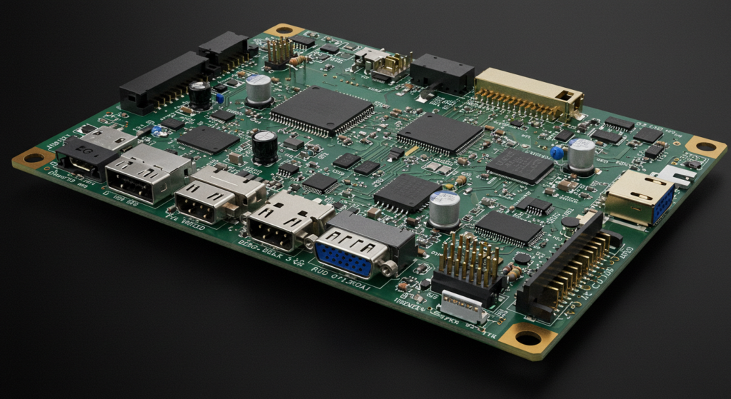
Core components include a microcontroller, signal converters, voltage regulators, input/output ports, and sometimes memory.
Main Parts
- Microcontroller or IC: The “brain” that manages all signals.
- Voltage Regulator: Ensures the LCD receives the correct voltage.
- Signal Converter: Converts data formats as needed.
- Connectors: For power, data, and control signals.
- Optional Memory: Stores image data or firmware.
Example Component List
Timing is crucial. The board generates clock signals to synchronize the display refresh rate. For example, a mismatch here causes flicker or image tearing. Data signals are then converted to the voltage and format the LCD needs.
In a project I handled, a client’s display had ghosting. The issue turned out to be timing misalignment in the controller board. After adjusting the timing IC settings, the image became crisp and stable.
| Component | Role |
|---|---|
| Main IC | Controls signal processing |
| Power Supply IC | Regulates voltage |
| Backlight Driver | Manages LED backlight |
| LVDS/TTL Converter | Converts signal formats |
| EEPROM/Flash | Stores firmware/settings |
Each part is vital. A missing or faulty component can lead to failure.
What Types of LCD Controller Boards Exist?
I get this question from new engineers: “Are all controller boards the same?” The answer is no.
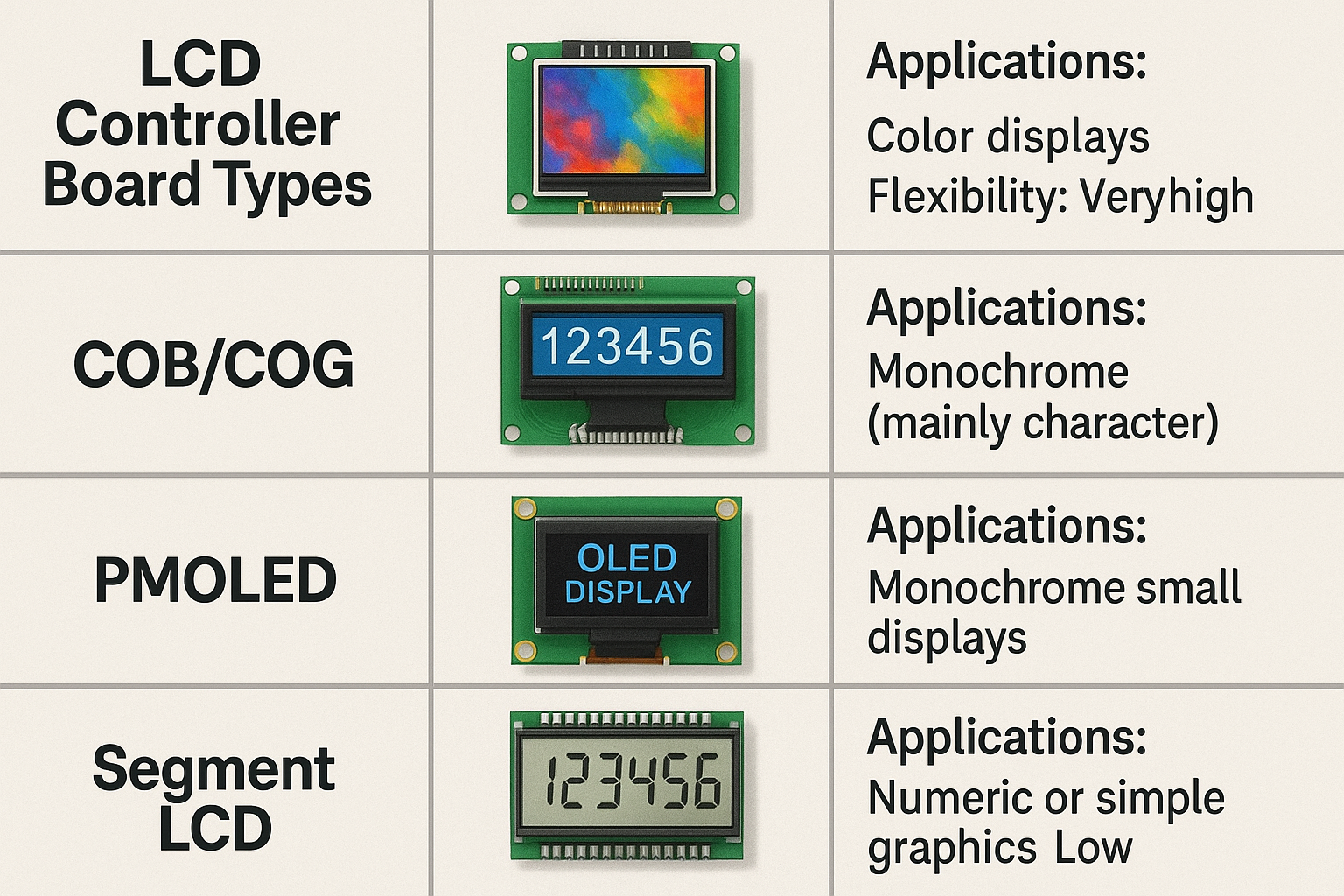
There are general-purpose, custom, and specialized controller boards for different display technologies and sizes.
Classifying Controller Boards
1. By Display Technology
2. By Application
- General-Purpose: Works with multiple panel types.
- Custom/OEM: Made for specific panels or customers.
- Smart Controller Boards: With touch or wireless functions.
Board Types Comparison
| Type | Application | Flexibility |
|---|---|---|
| General Purpose | Prototyping, testing | High |
| Custom/OEM | Volume production | Medium |
| Specialized | Unique requirements | Low |
How Do You Determine LCD Controller Board Compatibility?
This is a question I hear from buyers: “Will this controller work with my LCD?” Compatibility checks are critical.
Check signal type, voltage levels, display resolution, connector type, and supported functions for compatibility.
The Steps to Verify Compatibility

Main Factors
- Signal Interface: Match LVDS, TTL, HDMI, etc(Comprehensive Guide to LCD Interface Modes).
- Voltage: Both board and LCD must operate within the same voltage range(What Is the Right Way to Use Level Shifters With 3.3V LCD Modules in 5V Systems?).
- Resolution: Controller must support the display’s pixel matrix(How much does the resolution of the LCD screen affect the image quality?).
- Connector Pinout: Alignment of pins and signals.
- Special Functions: Touch support, backlight control(Why Do Automotive Displays Require Specialized Interface Protocols?).
My Practical Tip
When evaluating a new LCD and board, I always check the datasheets side by side and use a checklist like this:
| Checkpoint | LCD Module | Controller Board | Match (Y/N) |
|---|---|---|---|
| Signal Type | LVDS | LVDS | Y |
| Voltage | 3.3V | 3.3V | Y |
| Resolution | 800×480 | 800×480 | Y |
| Backlight Control | PWM | PWM | Y |
Never skip compatibility checks, even for similar models.
What Interface Standards Do LCD Controller Boards Support?
Many customers wonder, “Which interfaces are supported?” There are several options, each for different needs(What Are the Differences Between LVDS and MIPI-DSI Interfaces?).
LCD controller boards support standards like TTL, LVDS, HDMI, MIPI, eDP, SPI, and I2C.
Popular Interfaces
- TTL (Transistor-Transistor Logic)
- LVDS (Low Voltage Differential Signaling)
- HDMI (High-Definition Multimedia Interface)
- MIPI DSI (Mobile Industry Processor Interface Display Serial Interface)
- eDP (Embedded DisplayPort)
- SPI/I2C (Serial interfaces for simple displays)
Interface Comparison
What Are Common LCD Controller Board Applications?
I often get asked, “Where are these boards used?” The answer is almost everywhere you see a display.
LCD controller boards power devices like monitors, medical instruments, industrial panels, handhelds, and smart home gadgets.
Main Application Areas
- Industrial equipment: Machine control panels, test instruments
- Consumer devices: TV screens, monitors, tablets
- Medical equipment: Patient monitors, diagnostic tools
- Automotive: Instrument clusters, infotainment
- Home appliances: Smart ovens, washing machines
Applications Overview
| Application | Example Product | Importance |
|---|---|---|
| Industrial | HMI Panels | High |
| Medical | Ultrasound display | Critical |
| Automotive | Car dashboard | High |
| Consumer electronics | E-book reader | Medium |
The flexibility of controller boards lets them fit nearly any product needing a display.
What Are the Performance Considerations for LCD Controller Boards?
People ask me, “What should I look for in a high-performance board?” Here’s what matters most.
Key factors include refresh rate, resolution, color depth, response time, reliability, and power efficiency.
How Performance Impacts Products
1. Important Metrics
- Refresh Rate: Smooth visuals, critical for video or gaming.
- Color Depth: Accurate color reproduction.
- Response Time: Fast display updates, no ghosting.
- Reliability: Consistent operation in tough environments.
- Power Use: Low power for portable devices.
2. Performance Metrics
| Metric | Impact | Typical Value |
|---|---|---|
| Refresh Rate | Visual smoothness | 60-120Hz |
| Color Depth | Image quality | 16-bit, 24-bit |
| Response Time | Image clarity | <10ms |
| Power Use | Battery life | <1W for small modules |
High performance is about balance. I often discuss trade-offs with customers, especially in industrial or portable designs.
How Do LCD Controller Boards Enable Advanced Features?
Trends include AI integration, ultra-low power, miniaturization, flexible interfaces, and edge computing capabilities.
Innovations Shaping the Market
1. Key Trends
- AI Integration: Boards handle image processing, recognition, and real-time analysis
- Power Efficiency: Focus on lower energy use for wearables, IoT
- Smaller Size: Compact boards for smaller devices
- Flexible, Modular Interfaces: Mix and match interface modules
- Edge Computing: Local data processing, less reliance on cloud
2. Future-Focused Features
| Trend | Value | Example Use Case |
|---|---|---|
| AI Integration | Smart, adaptive displays | Retail ads, security |
| Ultra-low Power | Long battery life | IoT, remote sensors |
| Modular Interfaces | Easy upgrades | Industrial controls |
| Edge Computing | Real-time, offline use | Medical, automotive |
Staying updated with these trends helps you select future-proof controller boards.
Conclusion
An LCD controller board is an essential circuit board that acts as the interpreter between your video source (like a computer) and the raw LCD panel, making it possible to display an image.
FAQ
What should I do if my LCD controller board is not recognized by the main system?
Check the interface connection and make sure the board is powered and compatible with your system’s signals.
Can LCD controller boards be repaired if damaged?
Minor faults like fuse or connector damage can be fixed, but most core IC failures require a replacement board.
Is firmware update possible for LCD controller boards?
Some controller boards support firmware updates, which can add functions or fix bugs, but check your board’s documentation.
How do I prevent overheating in LCD controller boards during operation?
Ensure proper ventilation, avoid blocking airflow, and consider using a heat sink or fan in high-power designs.
Are there controller boards that support both touch and non-touch LCDs?
Yes, many modern boards have optional touch controller integration, so they work with both touch and non-touch panels.